NASA Completes Key Step in Aviation Safety Research

NASA Completes Key Step in Aviation Safety Research

4 min read

NASA Completes Key Step in Aviation Safety Research

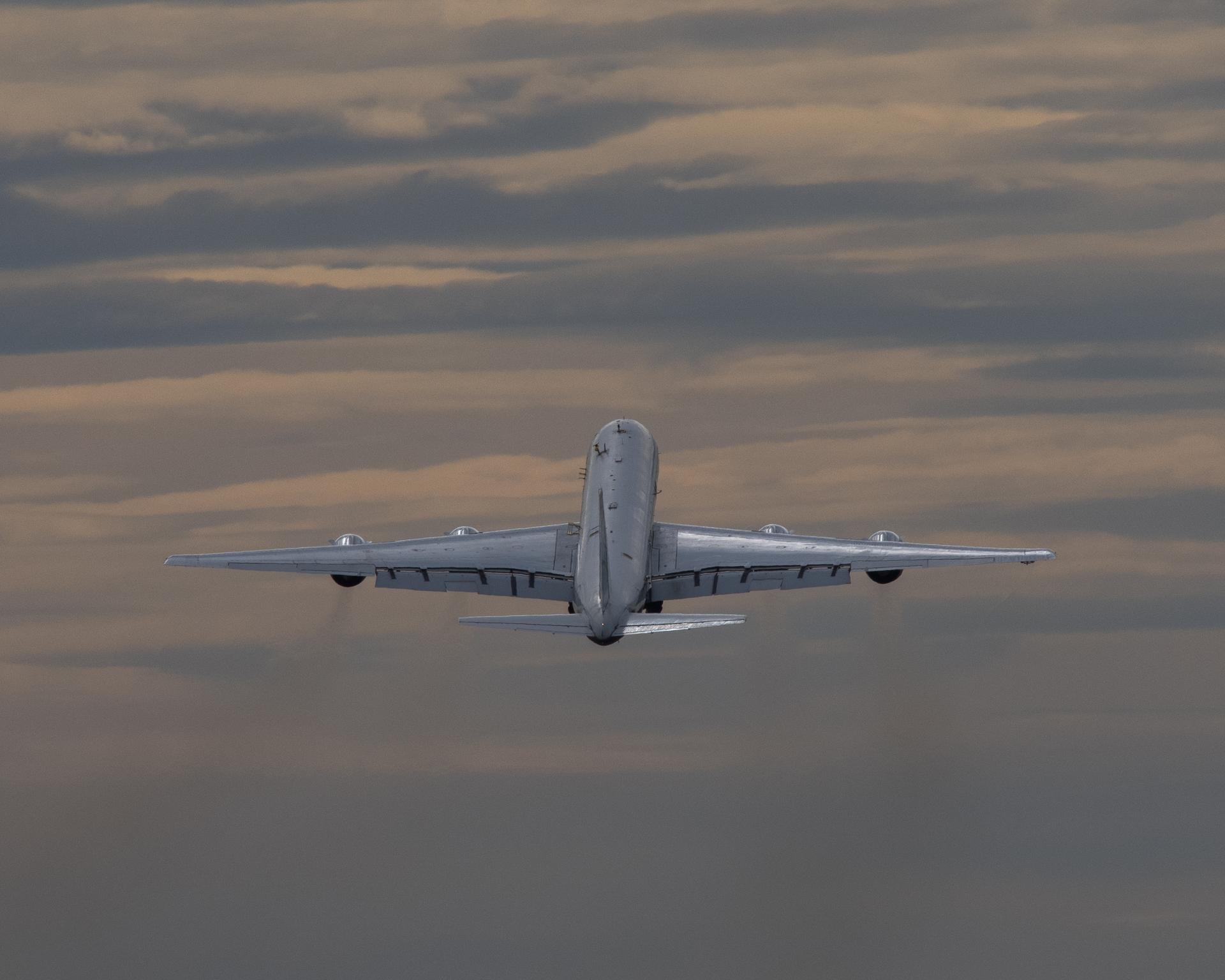
Artist concept showing various projects the SWS team works on, from developing new data solutions, new technology and the safety risks associated with it, from robotics to unmanned aircraft and more.
NASA’s transformational vision for the skies above our communities includes enabling safer and more efficient air travel. Part of this goal involves using advanced new technology to prevent safety risks long before they have a chance to arise.
MTSI / NASA

NASA’s aeronautical innovators have completed a significant step in their pursuit of safer, more efficient aviation technologies that spot hazards before they occur.

Through its System-Wide Safety project, NASA and its partners in government, industry, and academia are exploring new technologies and techniques to improve current aviation safety and potentially enable widespread use of new types of aircraft such as drones or air taxis.

The project recently completed Technical Challenge 1 (TC-1), Terminal Area Risk Management, the first step towards achieving what is known as an In-Time Aviation Safety Management System. This new type of aviation safety technology can effectively address potential hazards expected with the rise in demand for the number and types of aircraft flying in the National Airspace System.

As aviation operations continue to grow in scale and diversity, and with new modes of flight expected to rise in the near future, keeping the skies safe becomes increasingly complex and drives the need to transform the way order is maintained above our communities.

“What we’ve accomplished with TC-1 is really just beginning to scratch the surface of what’s possible,” said Kyle Ellis, NASA’s project manager for System-Wide Safety. “Developing these systems enables a new economy for aviation uses that will benefit us all in the future.”

Planning Ahead

In a busy aviation environment, an In-Time Aviation Safety Management System can efficiently identify and predict safety issues a human would be hard tasked to keep up with.

In today’s airspace safety system, let’s say an air traffic manager is looking at their screen and guiding 10 airplanes towards their destinations. This person would use a combination of established safety rules and pattern recognition to make sure those aircraft remain a safe distance apart. If this person saw a hazard that posed a safety risk, they would work with the pilots aboard the aircraft and resolve the issue.

Now, let’s think about the airspace of tomorrow. Instead of 10 airplanes total, 10 air taxis, 10 ultra-efficient airliners, and 10 commercial supersonic jets might be sharing the same confined airspace. Preventing and addressing hazards would become a more complex issue nearly impossible for a person to identify in time to prevent an accident.

An In-Time Aviation Safety Management System is designed to identify these events much more rapidly than human operators, then quickly deliver actionable safety procedures to prevent the dangerous situation long before it develops.

Furthermore, preventing these situations from ever arising in the first place increases the efficiency of the airspace overall, since not as much time and effort would be spent by managers keeping things running smoothly.

Laying the Foundation

TC-1 contributed several important pieces of technology working towards the development of such a system. These contributions improve aviation safety not just for tomorrow – but also for today.

For example, part of the research included using new machine learning algorithms to analyze data gathered from major airlines, which use existing aviation safety management systems, to discover potential safety risks that had previously been undefined – overall making things safer.

Researchers also gathered information on exact ways human safety managers, pilots, air traffic controllers, and others interact with safety procedures. The team identified useful, efficient practices, as well as those that could potentially lead to safety risks. Their work contributes substantially to improving training and safety operations.

Additionally, researchers studied human performance and fatigue, partnering with pilots to study how various factors such as flight scheduling, certain short-haul routes, and even the COVID-19 pandemic affect operations.

Other results include prototype safety tools and surveys on human performance.

With this more comprehensive understanding of the safety landscape, NASA and its partners can more effectively continue ushering in new safety technologies.

“We focused on gathering data on current-day operations, but always have an eye for the near future,” said Nikunj Oza, subproject manager for TC-1. “We can use the lessons learned about current aviation safety to best inform new systems.”

Share

Details

Last Updated

Nov 02, 2023

Editor

Lillian Gipson

Contact

Jim Banke
jim.banke@nasa.gov

Powered by WPeMatico

Get The Details…
Lillian Gipson

NASA’s Lucy Spacecraft Discovers 2nd Asteroid During Dinkinesh Flyby

NASA’s Lucy Spacecraft Discovers 2nd Asteroid During Dinkinesh Flyby

3 min read

NASA’s Lucy Spacecraft Discovers 2nd Asteroid During Dinkinesh Flyby

On Nov. 1, NASA’s Lucy spacecraft flew by not just its first asteroid, but its first two. The first images returned by Lucy reveal that the small main belt asteroid Dinkinesh is actually a binary pair.

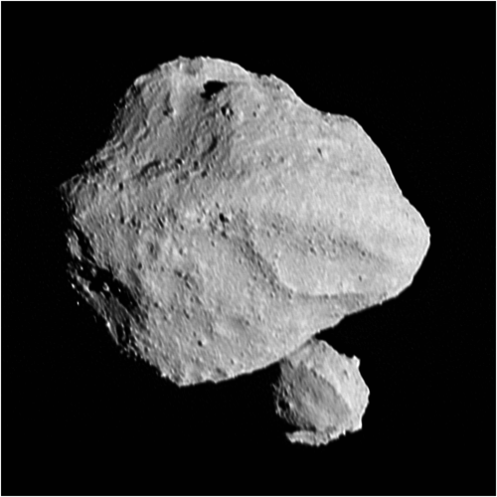
An image of asteroid Dinkinesh, a pair of grey asteroids with a slightly jagged surface, taken from the Lucy spacecraft.
This image shows the “moonrise” of the satellite as it emerges from behind asteroid Dinkinesh as seen by the Lucy Long-Range Reconnaissance Imager (L’LORRI), one of the most detailed images returned by NASA’s Lucy spacecraft during its flyby of the asteroid binary. This image was taken at 12:55 p.m. EDT (1655 UTC) Nov. 1, 2023, within a minute of closest approach, from a range of approximately 270 miles (430 km). From this perspective, the satellite is behind the primary asteroid. The image has been sharpened and processed to enhance contrast.
NASA/Goddard/SwRI/Johns Hopkins APL/NOAO

“Dinkinesh really did live up to its name; this is marvelous,” said Hal Levison, referring to the meaning of Dinkinesh in the Amharic language, “marvelous.” Levison is principal investigator for Lucy from the Boulder, Colorado, branch of the San-Antonio-based Southwest Research Institute. “When Lucy was originally selected for flight, we planned to fly by seven asteroids. With the addition of Dinkinesh, two Trojan moons, and now this satellite, we’ve turned it up to 11.”

In the weeks prior to the spacecraft’s encounter with Dinkinesh, the Lucy team had wondered if Dinkinesh might be a binary system, given how Lucy’s instruments were seeing the asteroid’s brightness changing with time. The first images from the encounter removed all doubt. Dinkinesh is a close binary. From a preliminary analysis of the first available images, the team estimates that the larger body is approximately 0.5 miles (790 m) at its widest, while the smaller is about 0.15 miles (220 m) in size.

This encounter primarily served as an in-flight test of the spacecraft, specifically focusing on testing the system that allows Lucy to autonomously track an asteroid as it flies past at 10,000 mph, referred to as the terminal tracking system.

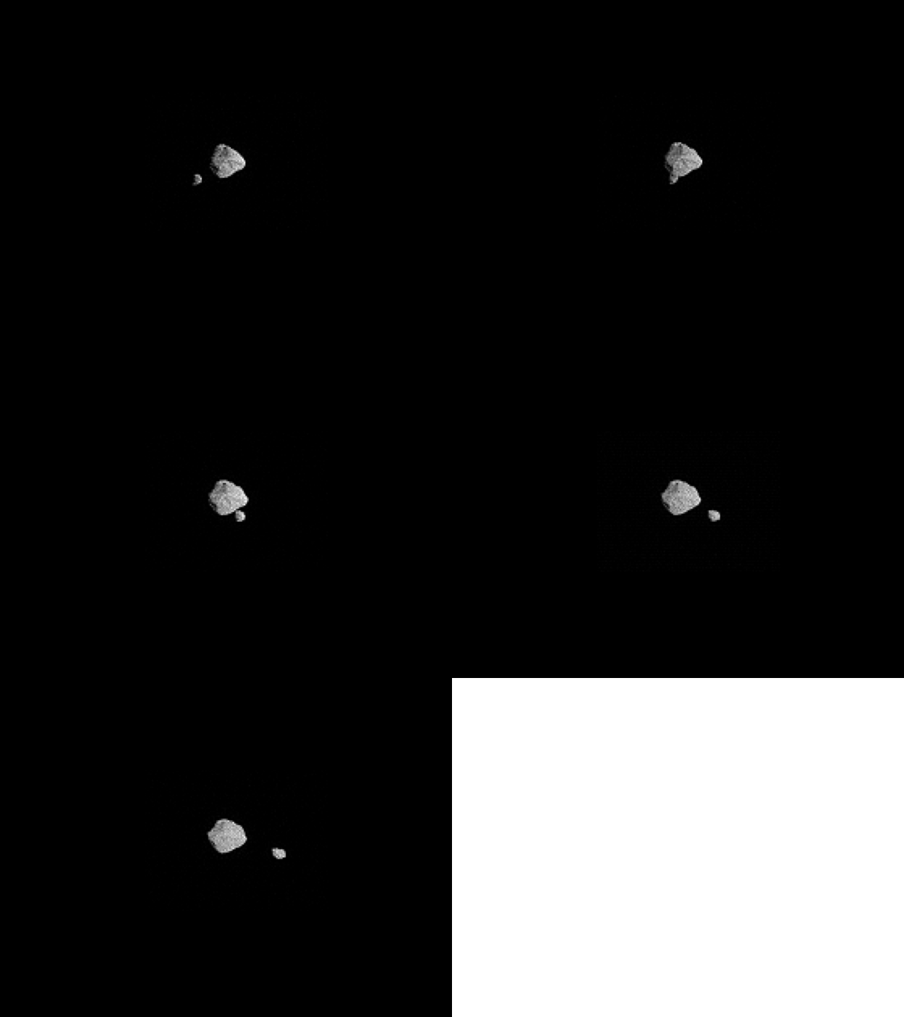
An animated gif of a a series of image taken from the Lucy spacecraft of a pair of asteroids named Dinkinesh. One asteroid is larger than the other, with the small one moving along the bottom of the larger asteroid from left to right as the Lucy spacecraft passes by.
A series of images of the binary asteroid pair, Dinkinesh, as seen by the terminal tracking camera (T2CAM) on NASA’s Lucy spacecraft during its closest approach on Nov. 1, 2023. The images were taken 13 seconds apart. The apparent motion of the two asteroids is due to the motion of the spacecraft as it flew past at 10,000 mph (4.5 km/s). These images have been sharpened and processed to enhance contrast.
NASA/Goddard/SwRI/ASU

“This is an awesome series of images. They indicate that the terminal tracking system worked as intended, even when the universe presented us with a more difficult target than we expected,” said Tom Kennedy, guidance and navigation engineer at Lockheed Martin in Littleton, Colorado. “It’s one thing to simulate, test, and practice. It’s another thing entirely to see it actually happen.”

While this encounter was carried out as an engineering test, the team’s scientists are excitedly poring over the data to glean insights into the nature of small asteroids.

“We knew this was going to be the smallest main belt asteroid ever seen up close,” said Keith Noll, Lucy project scientist from NASA’s Goddard Space Flight Center in Greenbelt, Maryland. “The fact that it is two makes it even more exciting. In some ways these asteroids look similar to the near-Earth asteroid binary Didymos and Dimorphos that DART saw, but there are some really interesting differences that we will be investigating.”

It will take up to a week for the team to downlink the remainder of the encounter data from the spacecraft. The team will use this data to evaluate the spacecraft’s behavior during the encounter and to prepare for the next close-up look at an asteroid, the main belt asteroid Donaldjohanson, in 2025. Lucy will then be well-prepared to encounter the mission’s main targets, the Jupiter Trojan asteroids, starting in 2027.

By Katherine Kretke
Southwest Research Institute, San Antonio

Media contact: Nancy N. Jones
NASA’s Goddard Space Flight Center, Greenbelt, Md.

Share

Details

Last Updated

Nov 02, 2023

Editor

Jamie Adkins

Contact

Powered by WPeMatico

Get The Details…
Jamie Adkins

NASA Goddard’s ‘Spiky’ Antenna Chamber: Signaling Success for 50 Years

NASA Goddard’s ‘Spiky’ Antenna Chamber: Signaling Success for 50 Years

3 min read

NASA Goddard’s ‘Spiky’ Antenna Chamber: Signaling Success for 50 Years

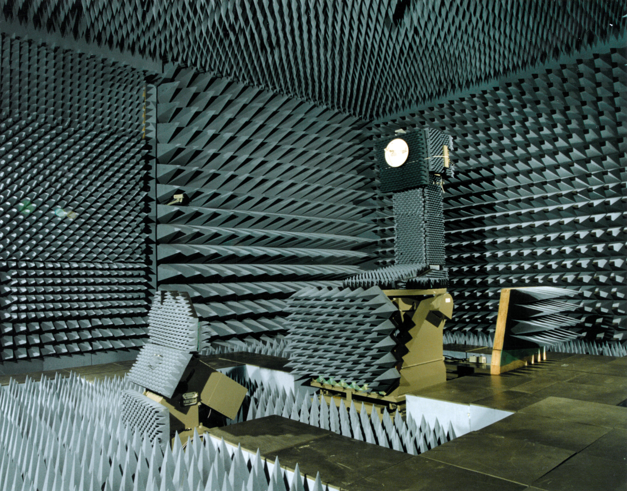
a room with blue-gray polyurethane spires covering the walls, ceiling and much of the floor. A center column supports a white antenna dish
The ElectroMagnetic Anechoic Chamber, GEMAC for short, at NASA’s Goddard Space Flight Center in Greenbelt, Maryland, has been a critical proving ground for antenna technology for more than half-a-century.
NASA

On any given day, NASA’s networks may communicate with over 100 space missions. Whether the mission keeps the lines of communication open with orbiting astronauts or peers deep into the cosmos, those dozens of satellites all have one thing in common: each needs an antenna. Without one, NASA missions and their discoveries simply would not be possible.

To ensure those antennas are up to the challenges of spaceflight, for most that means rigorous testing on the ground in a simulated space environment. The Goddard ElectroMagnetic Anechoic Chamber (GEMAC) at NASA’s Goddard Space Flight Center in Greenbelt, Maryland, has been an integral antenna proving ground for more than 50 years.

‘Sound Booth’ for Space Signals

Rows upon rows of cobalt-blue spires in Goddard’s antenna chamber evoke a soundproof room or isolation booth from a recording studio. In some ways the chamber is similar, but instead of dampening sound waves, this facility blocks out radio signals and eliminates radio wave reflections inside the chamber – “anechoic” means no echoes.

Much like laying down tracks on a hit album, errant ambient noise picked up by the microphone can ruin an otherwise perfect take. The same is true with radio waves when engineers want to test a spacecraft antenna. The radio environment on Earth is “noisy”: AM and FM broadcasts, television signals, cell phones, even microwave ovens, all produce radio frequencies – RF. To simulate the relatively tranquil RF environment of space, engineers need a way to isolate antennas from all these other Earth-based radio waves when they run their tests.

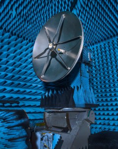
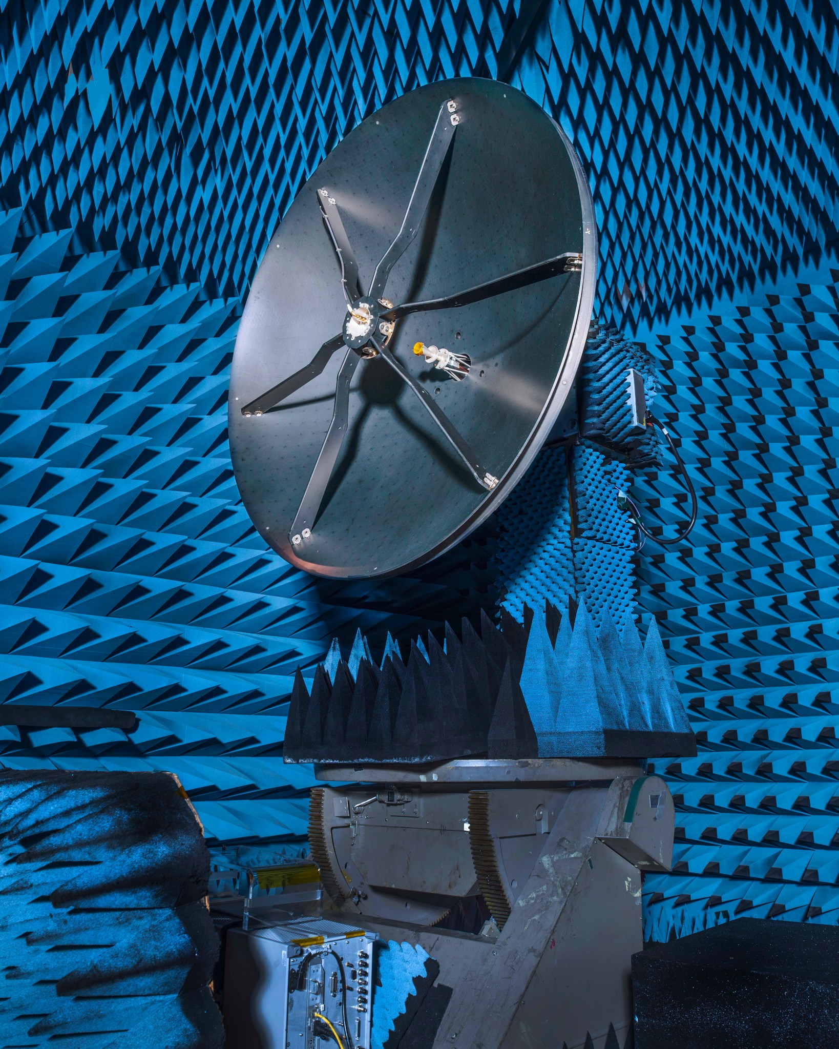
Roman’s high-gain antenna - a large, gray dish, about the height of a refrigerator, in a test chamber that is covered in blue spiked-shaped foam. A small circle is elevated in the middle of the antenna disk by six metal strips.
Engineers at NASA’s Goddard Space Flight Center in Greenbelt, Maryland, have finished testing the high-gain antenna for the Nancy Grace Roman Space Telescope. The antenna, shown here in Goddard’s ElectroMagnetic Anechoic Chamber in January 2023, will provide the primary communication link between the Roman spacecraft and the ground.
NASA / Chris Gunn

That’s the job of those tightly packed columns of spikes lining the floors and walls. These polyurethane foam cones are microwave absorbers. They block outside interference and noise, and within the chamber’s “quiet zone” as engineers call it, they provide a reflection-free environment like the antenna will experience in space.

Antennas Put to the Test

With this radio-proof environment, engineers at Goddard can accurately measure how efficiently antennas broadcast and receive signals. If an antenna’s signal were to go in unexpected or undesired directions during flight, it could mean the loss of mission data, or even the entire spacecraft itself if a critical command were missed.

Trying to do antenna design and testing work without a chamber like this “would be like taking a calculator away from an accountant,” said Goddard engineer Ken Hersey.

As NASA’s missions (and their antennas) have increased in sophistication over time, Goddard engineers have upgraded the anechoic chamber to follow suit. Hersey was a lead designer on the most recent major overhaul, which in 1997 expanded the range of antenna frequencies that could be accommodated in tests. The chamber can even help calibrate scientific instruments, like radars and microwave radiation sensors.

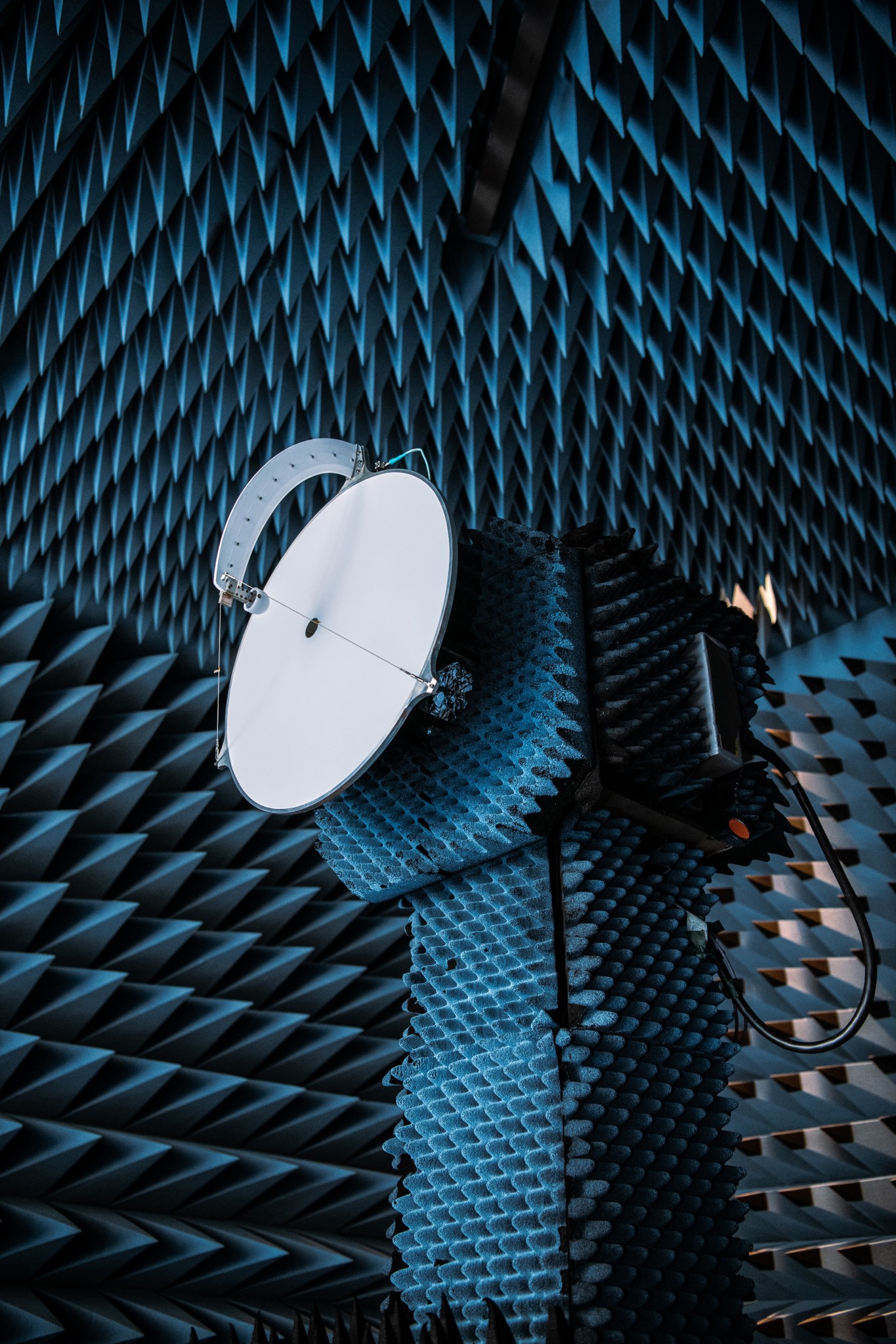
Testing of the PACE Earth Coverage Antenna. A circular white disk with a curved strip extending from its center to the edge of the disk is mounted on a stand, covered with gray foamy spikes to absorb sound. The entire room is also covered in gray foamy spikes, including the ceiling.
The Earth Coverage Antenna for NASA’s PACE – the Plankton, Aerosol, Cloud, ocean Ecosystem missionRadio frequency testing of the PACE Earth Coverage Antenna in the ElectroMagnetic Anechoic Chamber at Goddard Space Flight Center.
NASA’s Goddard Space Flight Center / Denny Henry

Most recently, the anechoic chamber certified both the Roman Space Telescope high-gain antenna and the Earth coverage antenna for PACE – the Plankton, Aerosol, Cloud, ocean Ecosystem mission. Launching by May 2027, Roman will have a field of view at least 100 times greater than Hubble’s and help settle essential questions about dark matter and dark energy. PACE launches in January 2024 on a mission to study Earth’s air quality, ocean health, and climate change.

Once these missions take flight, their groundbreaking observations will become the latest in an ongoing legacy of discoveries made possible with help from a battery of polyurethane cones and Goddard’s anechoic antenna chamber.

By Lauren Saloio
NASA’s Goddard Space Flight Center, Greenbelt, Md.

Media Contact:
Rob Garner
NASA’s Goddard Space Flight Center, Greenbelt, Md.

Share

Details

Last Updated

Nov 02, 2023

Editor

Rob Garner

Contact

Rob Garner
rob.garner@nasa.gov

Location

NASA Goddard Space Flight Center

Powered by WPeMatico

Get The Details…
Rob Garner

Workshop to Highlight NASA’s Support for Mobility, In-Space Servicing

Workshop to Highlight NASA’s Support for Mobility, In-Space Servicing

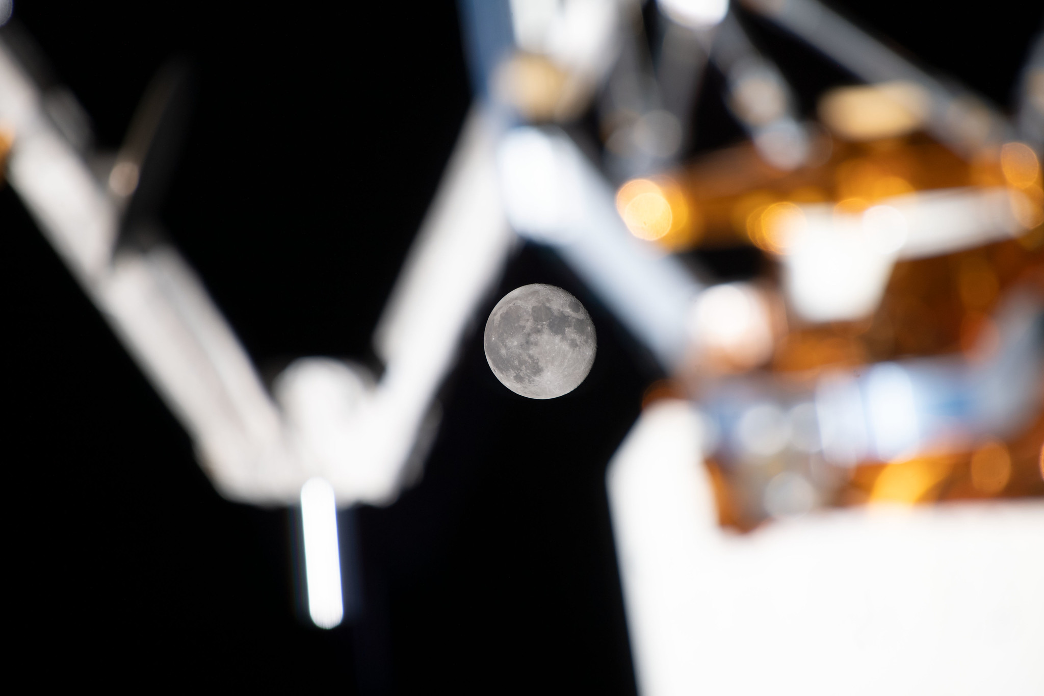
September's full Moon, the Harvest Moon, is photographed from the International Space Station, perfectly placed in between exterior station hardware.
September’s full Moon, the Harvest Moon, is photographed from the International Space Station, perfectly placed in between exterior station hardware.

NASA leadership, including Deputy Administrator Pam Melroy, will participate in a workshop on space mobility and in-space servicing on Tuesday, Nov. 7, at the University of Maryland in College Park.

Beginning at 8:30 a.m. EST, the Consortium for Space Mobility and ISAM Capabilities (COSMIC) workshop runs through Wednesday, Nov. 8. NASA announced the consortium in April, aiming to create a nationwide aerospace community alliance that provides global leadership in space mobility and in-space servicing, assembly, and manufacturing (ISAM) for use in Earth orbit, lunar orbit, deep space, and on planetary surfaces.

Following welcome remarks from Prasun Desai, acting associate administrator, Space Technology Mission Directorate at NASA Headquarters in Washington, Melroy will provide a keynote on NASA’s support for ISAM.

Other leaders from The White House Office of Science and Technology Policy, the U.S. Department of Defense, the defense and aerospace industry, and academia, also will participate. The conference features panel discussions and breakout workshops for COSMIC’s three caucuses ­– U.S. government, industry, and academia ­– and the Consortium’s five focus areas.

Media interested in attending the opening day, either in person or virtually, should RSVP by 12 p.m. on Monday, Nov. 6, to Parker Wishik at 708-391-7806 or parker.wishik@aero.org. NASA and COSMIC experts will be available for interview opportunities upon request. Other COSMIC plenary sessions will be recorded and later published to the COSMIC YouTube channel.

NASA funds COSMIC, creating a nationwide alliance around the capability areas, and it will support the ISAM National Strategy and National ISAM Implementation Plan, released in 2022, which define a national approach to build on existing investments and emerging capabilities to realize future opportunities enabled by ISAM. The Consortium aims to accelerate ISAM’s universal adoption and support its utilization as a routine part of space architectures and mission lifecycles.  

The Aerospace Corporation leads COSMIC as the management entity contracted by NASA’s Space Technology Mission Directorate to ensure coordination among members, caucuses, and focus areas and to execute COSMIC initiative-focused events.  

For information on the COSMIC kickoff meeting, including the full agenda, visit:

https://cosmicspace.org/2023/08/cosmics-kickoff-meeting

-end-

Jimi Russell
Headquarters, Washington
216-704-2412
james.j.russell@nasa.gov

Parker Wishik
COSMIC
708-391-7806
parker.wishik@aero.org

Powered by WPeMatico

Get The Details…
Jennifer M. Dooren

Details from Webb’s Cameras Reveal Crabby Composition

Details from Webb’s Cameras Reveal Crabby Composition

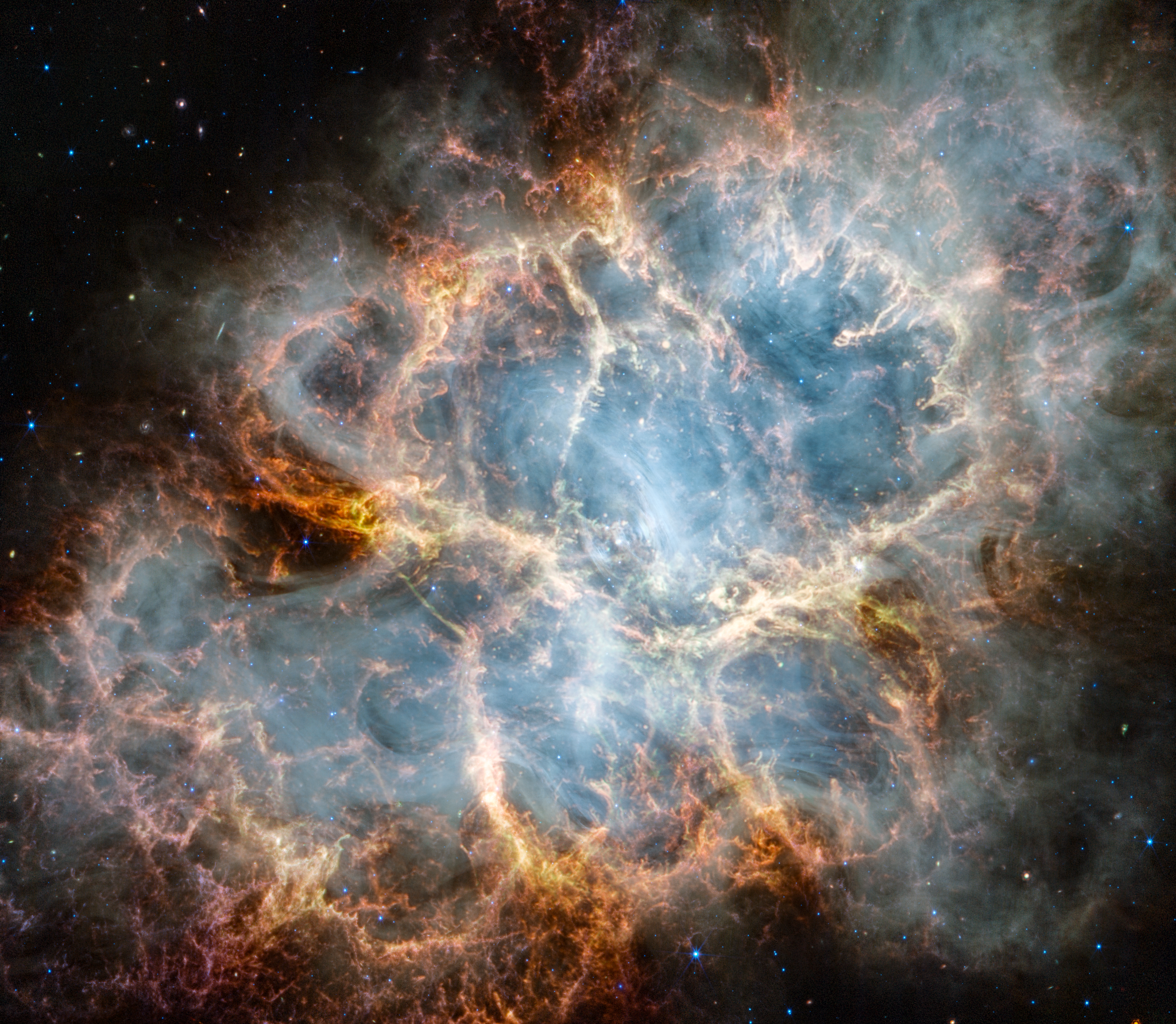
The Crab Nebula is an oval nebula with complex structure against a black background. On the nebula’s exterior, particularly at the top left and bottom left, lie curtains of glowing red and orange fluffy material. Its interior shell shows large-scale loops of mottled filaments of yellow-white and green, studded with clumps and knots. Translucent thin ribbons of smoky white lie within the remnant’s interior, brightest toward its center. The white material follows different directions throughout, including sometimes sharply curving away from certain regions within the remnant. A faint, wispy ring of white material encircles the very center of the nebula. Around and within the supernova remnant are many points of blue, red, and yellow light.
NASA, ESA, CSA, STScI, T. Temim (Princeton University)

The James Webb Space Telescope captures new details of the Crab Nebula, 6,500 light-years away, in this image released on Oct. 30, 2023. While these remains of an exploded star have been well-studied by multiple observatories, including the Hubble Space Telescope, Webb’s infrared sensitivity and resolution offer new clues into the makeup and origins of this scene.

Thanks to Webb’s Near-Infrared Camera (NIRCam) and Mid-Infrared Instrument (MIRI), scientists were able to determine the composition of the material ejected from the explosion. The supernova remnant is comprised of several different components, including doubly ionized sulfur (represented in red-orange), ionized iron (blue), dust (yellow-white and green), and synchrotron emission (white). In this image, colors were assigned to different filters from Webb’s NIRCam and MIRI: blue (F162M), light blue (F480M), cyan (F560W), green (F1130W), orange (F1800W), and red (F2100W).

Take a video tour of this image.

Image Credit: NASA, ESA, CSA, STScI, T. Temim (Princeton University)

Powered by WPeMatico

Get The Details…
Monika Luabeya