The story of how we understand planetary motion could not be told if it were not for the work of a German mathematician named Johannes Kepler.
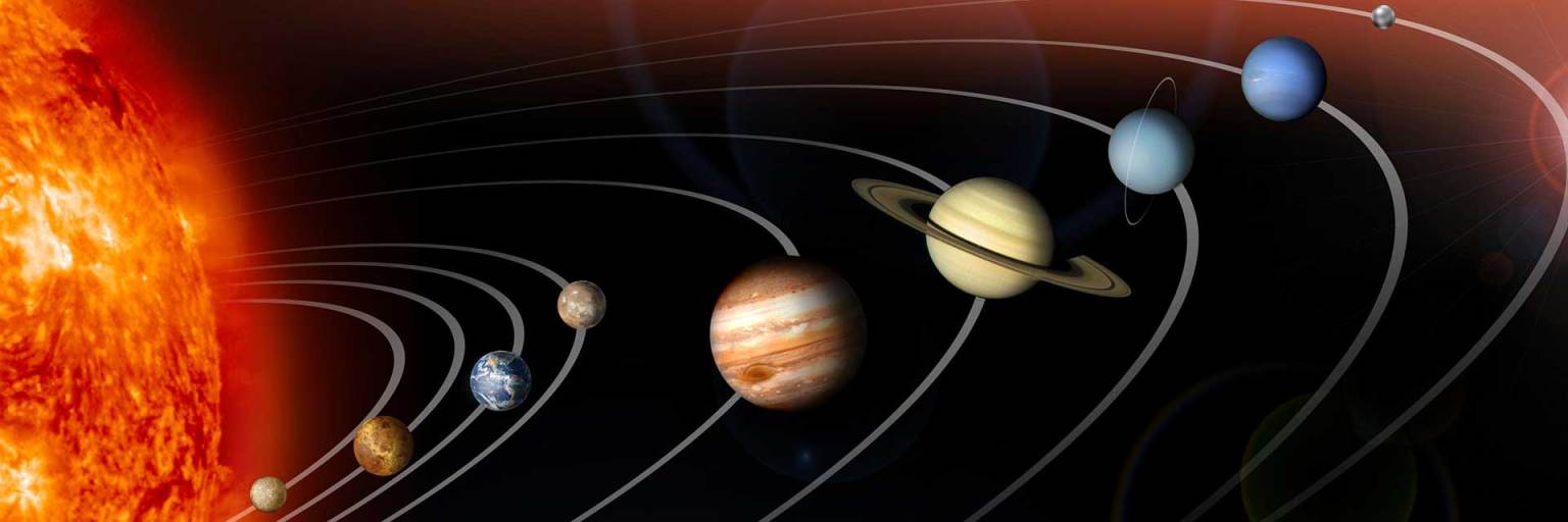
Kepler’s three laws describe how planets orbit the Sun. They describe how (1) planets move in elliptical orbits with the Sun as a focus, (2) a planet covers the same area of space in the same amount of time no matter where it is in its orbit, and (3) a planet’s orbital period is proportional to the size of its orbit.
The planets orbit the Sun in a counterclockwise direction as viewed from above the Sun’s north pole, and the planets’ orbits all are aligned to what astronomers call the ecliptic plane.
Who Was Johannes Kepler?
Johannes Kepler was born on Dec. 27, 1571, in Weil der Stadt, Württemberg, which is now in the German state of Baden-Württemberg.
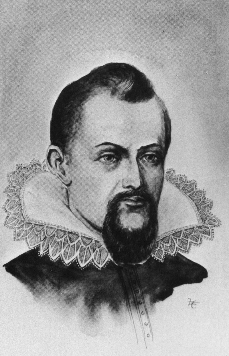
Johannes Kepler (1571-1630) was a German astronomer best known for determining three principles of how planets orbit the Sun, known as Kepler’s laws of planetary motion.
Courtesy of the Archives, California Institute of Technology
As a rather frail young man, the exceptionally talented Kepler turned to mathematics and the study of the heavens early on. When he was six, his mother pointed out a comet visible in the night sky. When Kepler was nine, his father took him out one night under the stars to observe a lunar eclipse. These events both made a vivid impression on Kepler’s youthful mind and turned him toward a life dedicated to astronomy.
Kepler lived and worked in Graz, Austria, during the tumultuous early 17th century. Due to religious and political difficulties common during that era, Kepler was banished from Graz on Aug. 2, 1600.
Fortunately, he found work as an assistant to the famous Danish astronomer Tycho Brahe (usually referred to by his first name) in Prague. Kepler moved his family from Graz, 300 miles (480 kilometers) across the Danube River to Tycho’s home.
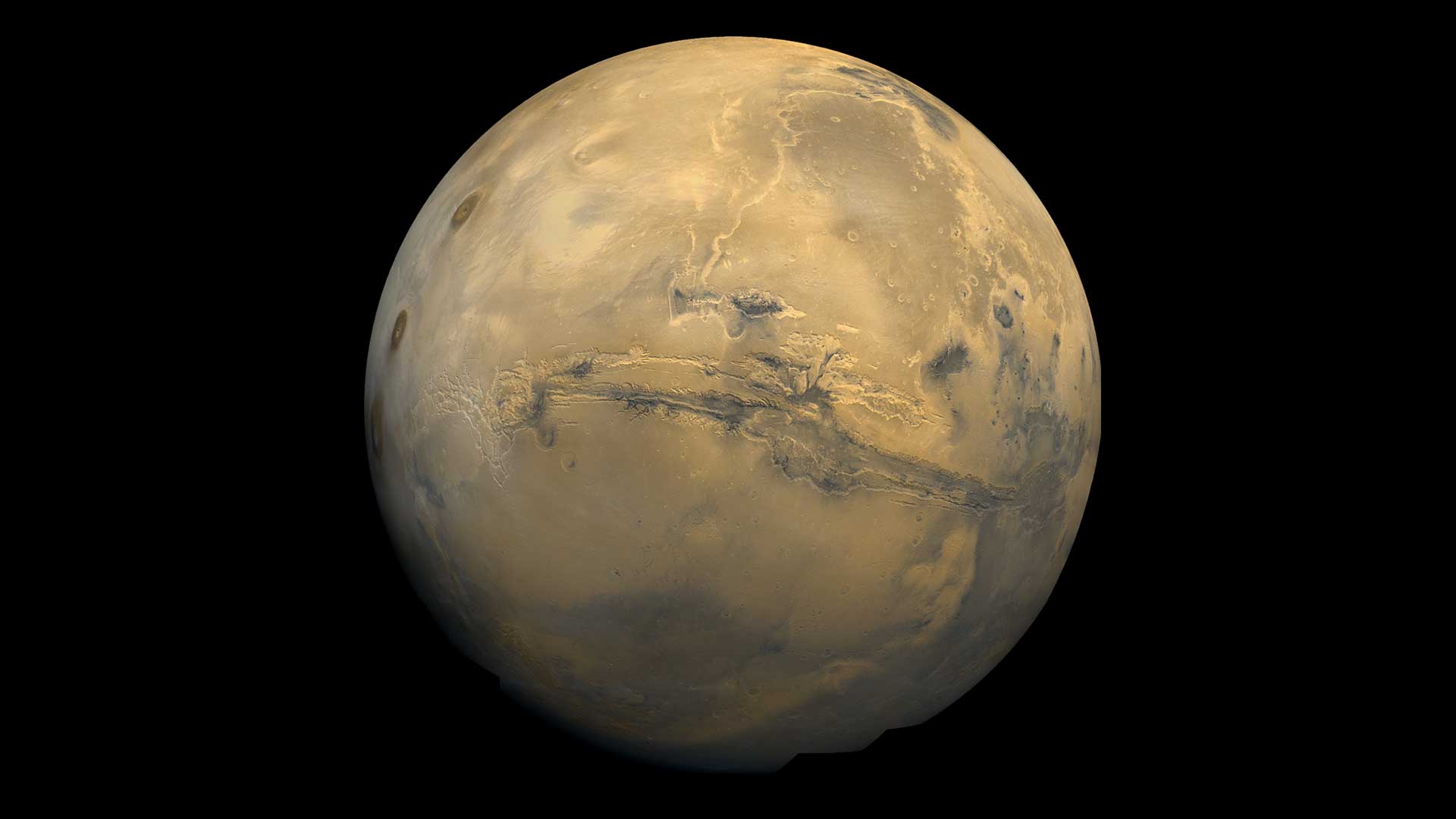
The global mosaic of Mars was created using Viking 1 Orbiter images taken in February 1980. The mosaic shows the entire Valles Marineris canyon system stretching across the center of Mars. It’s more than 2,000 miles (3,000 kilometers) long, 370 miles (600 kilometers) wide and 5 miles (8 kilometers) deep.
NASA
Kepler and the Mars Problem
Tycho was a brilliant astronomer. He is credited with making the most accurate astronomical observations of his time, which he accomplished without the aid of a telescope. He had been impressed with Kepler’s studies in an earlier meeting.
However, some historians think Tycho mistrusted Kepler, fearing that his bright young intern might eclipse him as the premier astronomer of his day. Because of this, he only let Kepler see part of his voluminous collection of planetary data.
Tycho assigned Kepler the task of understanding the orbit of the planet Mars. The movement of Mars was problematic – it didn’t quite fit the models as described by Greek philosopher and scientist Aristotle (384 to 322 B.C.E.) and Egyptian astronomer Claudius Ptolemy (about 100 C.E to 170 C.E.). Aristotle thought Earth was the center of the universe, and that the Sun, Moon, planets, and stars revolved around it. Ptolemy developed this concept into a standardized, geocentric model (now known as the Ptolemaic system) based around Earth as a stationary object, at the center of the universe.
Historians think that part of Tycho’s motivation for giving the Mars problem to Kepler was Tycho’s hope that it would keep Kepler occupied while Tycho worked to perfect his own theory of the solar system. That theory was based on a geocentric model, modified from Ptolemy’s, in which the planets Mercury, Venus, Mars, Jupiter, and Saturn all orbit the Sun, which in turn orbits Earth.
As it turned out, Kepler, unlike Tycho, believed firmly in a model of the solar system known as the heliocentric model, which correctly placed the Sun at its center. This is also known as the Copernican system, because it was developed by astronomer Nicolaus Copernicus (1473-1543). But the reason Mars’ orbit was problematic was because the Copernican system incorrectly assumed the orbits of the planets to be circular.
Like many philosophers of his era, Kepler had a mystical belief that the circle was the universe’s perfect shape, so he also thought the planets’ orbits must be circular. For many years, he struggled to make Tycho’s observations of the motions of Mars match up with a circular orbit.
Kepler eventually realized that the orbits of the planets are not perfect circles. His brilliant insight was that planets move in elongated, or flattened, circles called ellipses.
The particular difficulties Tycho had with the movement of Mars were due to the fact that its orbit was the most elliptical of the planets for which he had extensive data. Thus, in a twist of irony, Tycho unwittingly gave Kepler the very part of his data that would enable his assistant to formulate the correct theory of the solar system.
Basic Properties of Ellipses
Since the orbits of the planets are ellipses, it might be helpful to review three basic properties of an ellipse:
An ellipse is defined by two points, each called a focus, and together called foci. The sum of the distances to the foci from any point on the ellipse is always a constant.
The amount of flattening of the ellipse is called the eccentricity. The flatter the ellipse, the more eccentric it is. Each ellipse has an eccentricity with a value between zero (a circle), and one (essentially a flat line, technically called a parabola).
The longest axis of the ellipse is called the major axis, while the shortest axis is called the minor axis. Half of the major axis is termed a semi-major axis.
After determining that the orbits of the planets are elliptical, Kepler formulated three laws of planetary motion, which accurately described the motion of comets as well.
Kepler’s Laws
In 1609 Kepler published “Astronomia Nova,” which explained what are now called Kepler’s first two laws of planetary motion. Kepler had noticed that an imaginary line drawn from a planet to the Sun swept out an equal area of space in equal times, regardless of where the planet was in its orbit. If you draw a triangle from the Sun to a planet’s position at one point in time and its position at a fixed time later, the area of that triangle is always the same, anywhere in the orbit.
For all these triangles to have the same area, the planet must move more quickly when it’s near the Sun, but more slowly when it is farther from the Sun. This discovery became Kepler’s second law of orbital motion, and led to the realization of what became Kepler’s first law: that the planets move in an ellipse with the Sun at one focus point, offset from the center.
In 1619, Kepler published “Harmonices Mundi,” in which he describes his “third law.” The third law shows that there is a precise mathematical relationship between a planet’s distance from the Sun and the amount of time it takes revolve around the Sun.
Here are Kepler’s Three Laws:
Kepler’s First Law: Each planet’s orbit about the Sun is an ellipse. The Sun’s center is always located at one focus of the ellipse. The planet follows the ellipse in its orbit, meaning that the planet-to-Sun distance is constantly changing as the planet goes around its orbit.
Kepler’s Second Law: The imaginary line joining a planet and the Sun sweeps out – or covers – equal areas of space during equal time intervals as the planet orbits. Basically, the planets do not move with constant speed along their orbits. Instead, their speed varies so that the line joining the centers of the Sun and the planet covers an equal area in equal amounts of time. The point of nearest approach of the planet to the Sun is called perihelion. The point of greatest separation is aphelion, hence by Kepler’s second law, a planet is moving fastest when it is at perihelion and slowest at aphelion.
Kepler’s Third Law: The orbital period of a planet, squared, is directly proportional to the semi-major axes of its orbit, cubed. This is written in equation form as p2=a3. Kepler’s third law implies that the period for a planet to orbit the Sun increases rapidly with the radius of its orbit. Mercury, the innermost planet, takes only 88 days to orbit the Sun. Earth takes 365 days, while distant Saturn requires 10,759 days to do the same.
How We Use Kepler’s Laws Today
Kepler didn’t know about gravity, which is responsible for holding the planets in their orbits around the Sun, when he came up with his three laws. But Kepler’s laws were instrumental in Isaac Newton’s development of his theory of universal gravitation, which explained the unknown force behind Kepler’s third law. Kepler and his theories were crucial in the understanding of solar system dynamics and as a springboard to newer theories that more accurately approximate planetary orbits. However, his third law only applies to objects in our own solar system.
Newton’s version of Kepler’s third law allows us to calculate the masses of any two objects in space if we know the distance between them and how long they take to orbit each other (their orbital period). What Newton realized was that the orbits of objects in space depend on their masses, which led him to discover gravity.
Newton’s generalized version of Kepler’s third law is the basis of most measurements we can make of the masses of distant objects in space today. These applications include determining the masses of moons orbiting the planets, stars that orbit each other, the masses of black holes (using nearby stars affected by their gravity), the masses of exoplanets (planets orbiting stars other than our Sun), and the existence of mysterious dark matter in our galaxy and others.
In planning trajectories (or flight plans) for spacecraft, and in making measurements of the masses of the moons and planets, modern scientists often go a step beyond Newton. They account for factors related to Albert Einstein’s theory of relativity, which is necessary to achieve the precision required by modern science measurements and spaceflight.
However, Newton’s laws are still accurate enough for many applications, and Kepler’s laws remain an excellent guide for understanding how the planets move in our solar system.
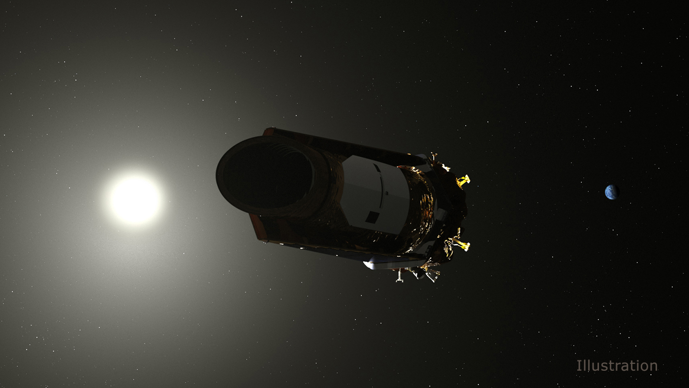
NASA’s Kepler space telescope discovered thousands of planets outside our solar system, and revealed that our galaxy contains more planets than stars.
NASA
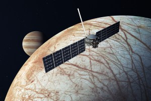
Johannes Kepler died Nov. 15, 1630, at age 58. NASA’s Kepler space telescope was named for him. The spacecraft launched March 6, 2009, and spent nine years searching for Earth-like planets orbiting other stars in our region of the Milky Way. The Kepler space telescope left a legacy of more than 2,600 planet discoveries from outside our solar system, many of which could be promising places for life.
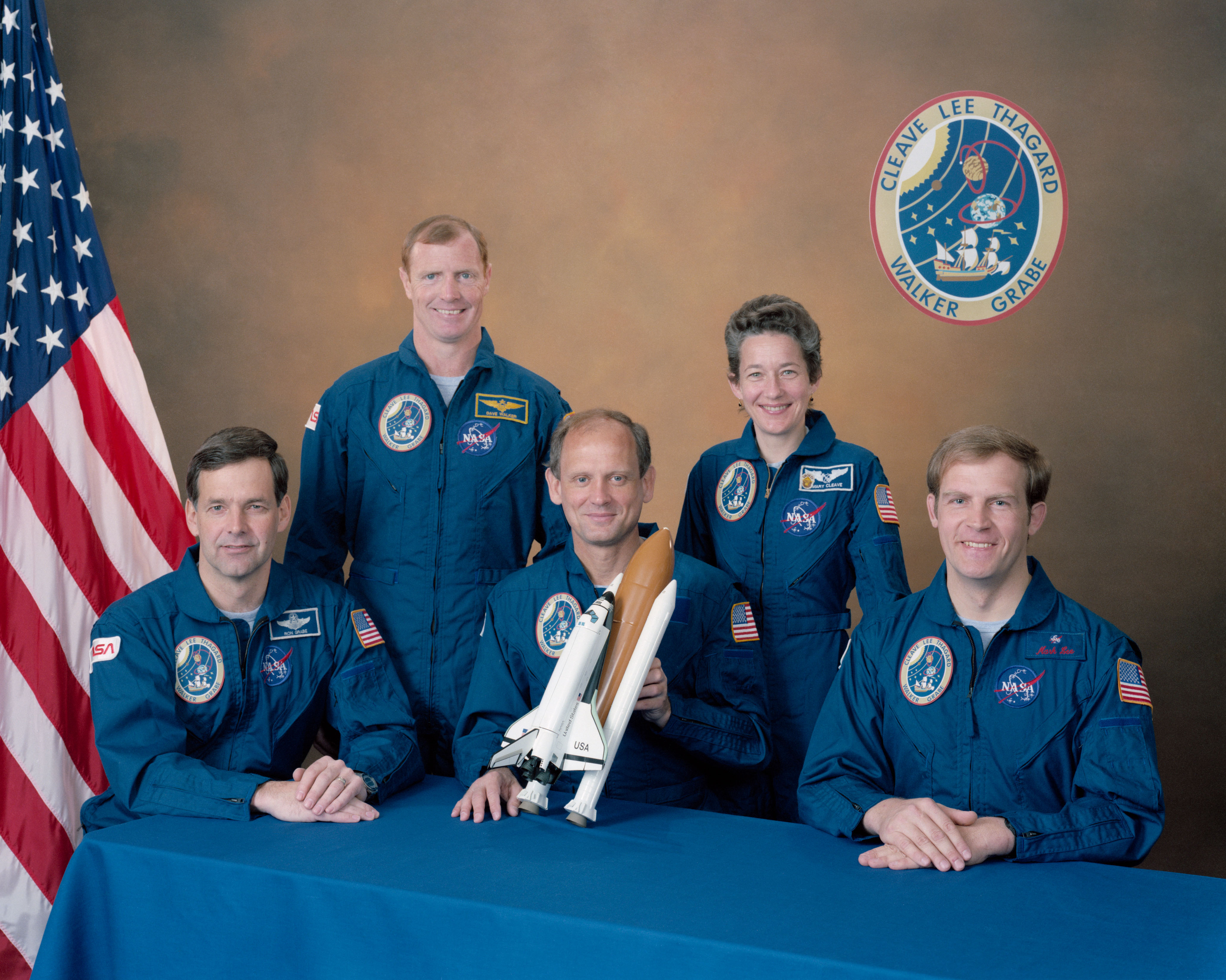
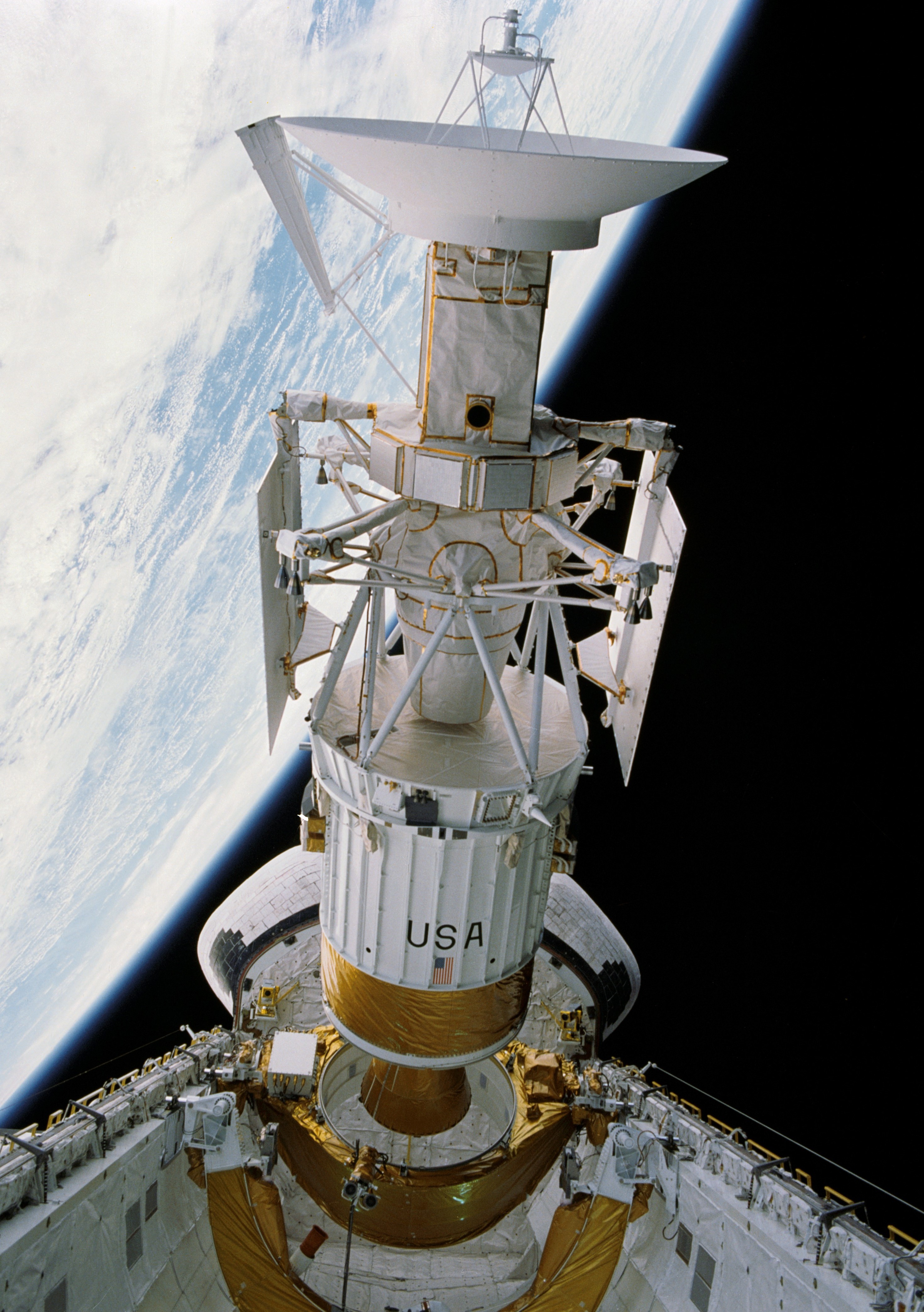
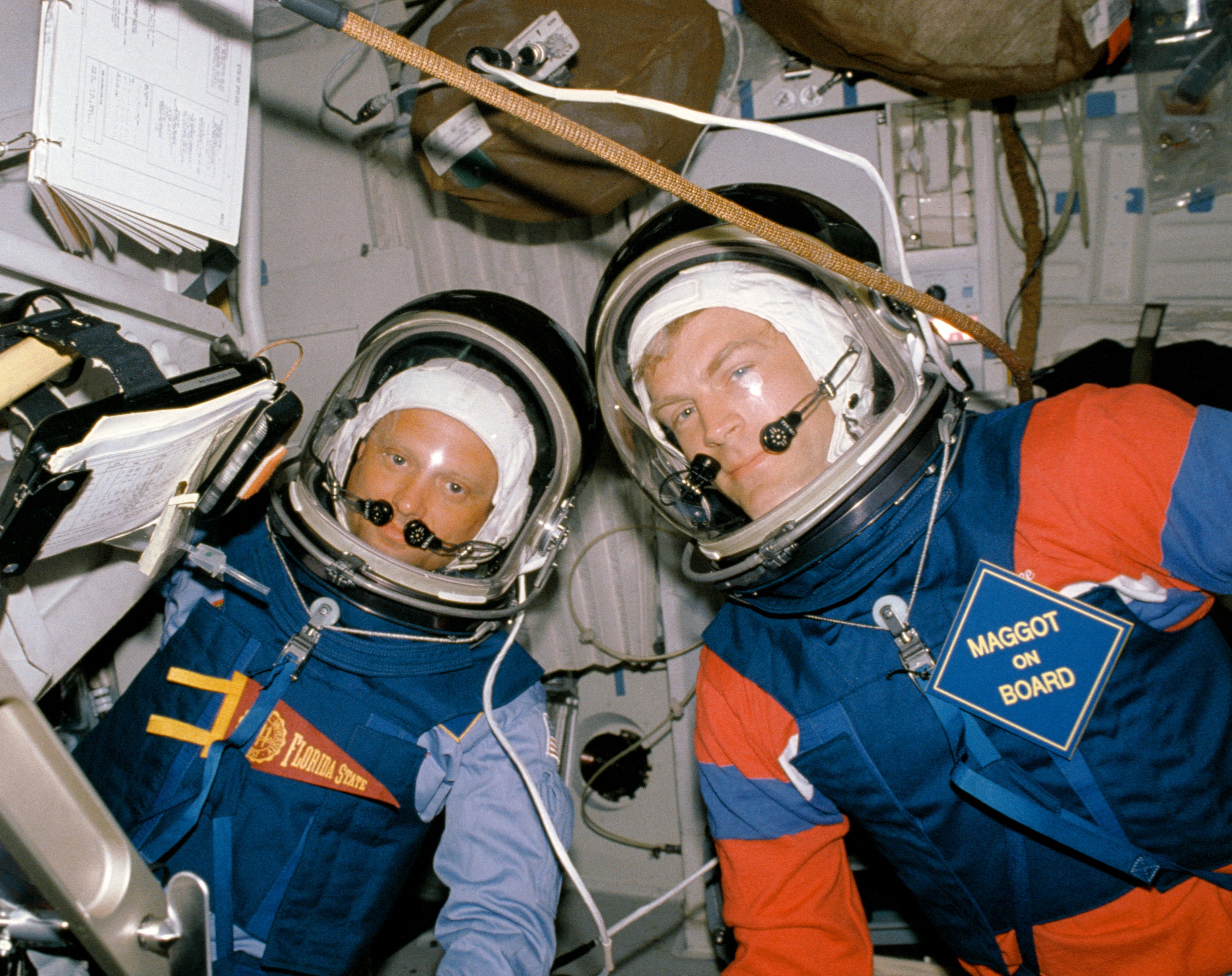
On May 4, 1989, space shuttle Atlantis took off on its third flight, STS-30, from NASA’s Kennedy Space Center (KSC) in Florida. Its five-person crew of Commander David M. Walker, Pilot Ronald J. Grabe, and Mission Specialists Mark C. Lee, Norman E. Thagard, and Mary L. Cleave flew a four-day mission that deployed the Magellan spacecraft, managed by NASA’s Jet Propulsion Laboratory in Southern California, to study Venus, uniting NASA’s human and interplanetary spaceflight programs. It also marked the first U.S. planetary launch since 1978. The astronauts deployed Magellan and its upper stage on their first day in space, sending the spacecraft on its 15-month journey to Venus. Following its arrival at the cloud-shrouded planet, Magellan spent four years mapping Venus in unprecedented detail, vastly increasing our knowledge of the planet.
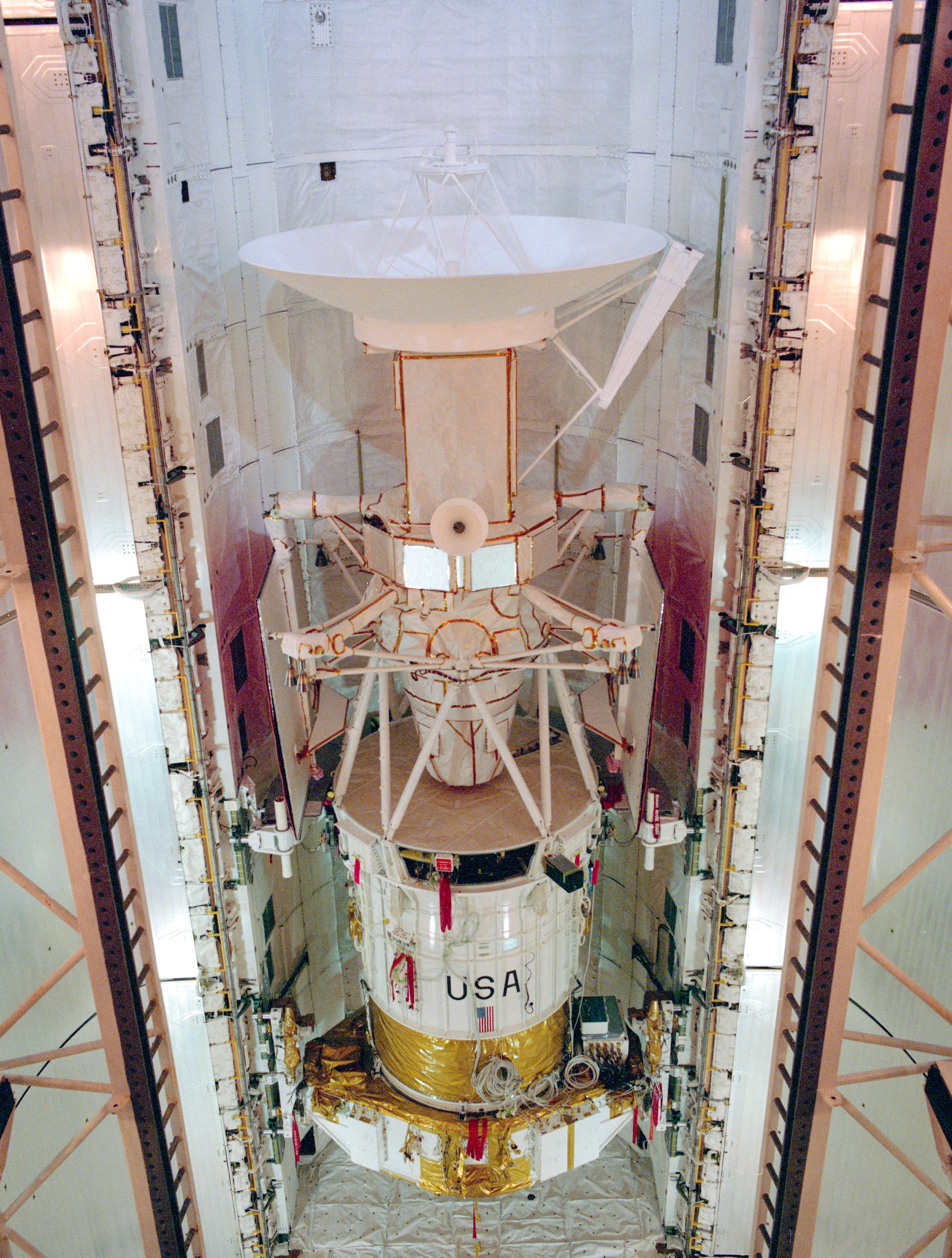
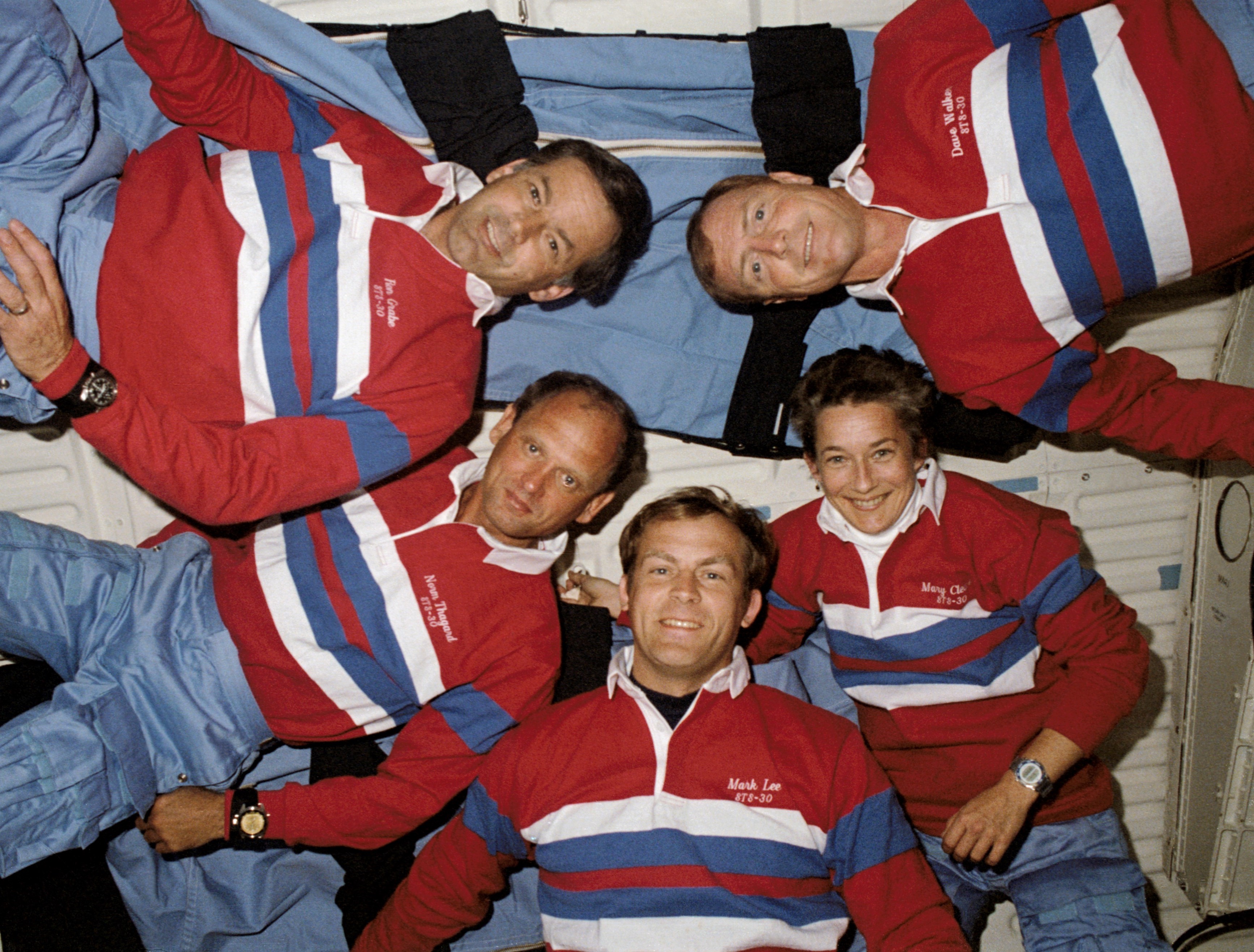
Left: The STS-30 crew of Pilot Ronald J. Grabe, left, Commander David M. Walker, and Mission Specialists Norman E. Thagard, Mary L. Cleave, and Mark C. Lee. Middle: The STS-30 crew patch. Right: The Magellan spacecraft in Atlantis’ payload bay in preparation for STS-30.
In March 1988, NASA announced Walker, Grabe, Lee, Thagard, and Cleave as the STS-30 crew for the flight planned for late April 1989. Thagard had flown twice before, on STS-7 in June 1983 and the STS-51B Spacelab 3 mission in April-May 1985. Walker, Grabe, and Cleave had each flown once before, on STS-51A, STS-51J, and STS-61B, respectively, while STS-30 marked Lee’s first trip into space. Walker and Thagard joined NASA in the astronaut class of 1978, Grabe and Cleave joined in 1980, and Lee in 1984. During their four-day mission, the astronauts planned to deploy Magellan and its Inertial Upper Stage (IUS) on the first flight day. Magellan needed to launch within a 29-day window, dictated by the alignments of Venus and Earth to achieve the proper trajectory for the journey to its destination.
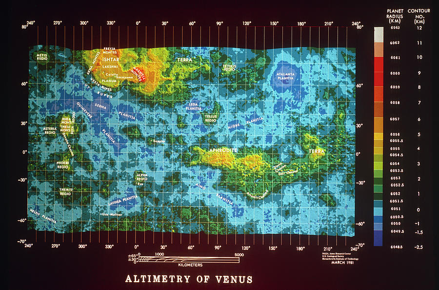
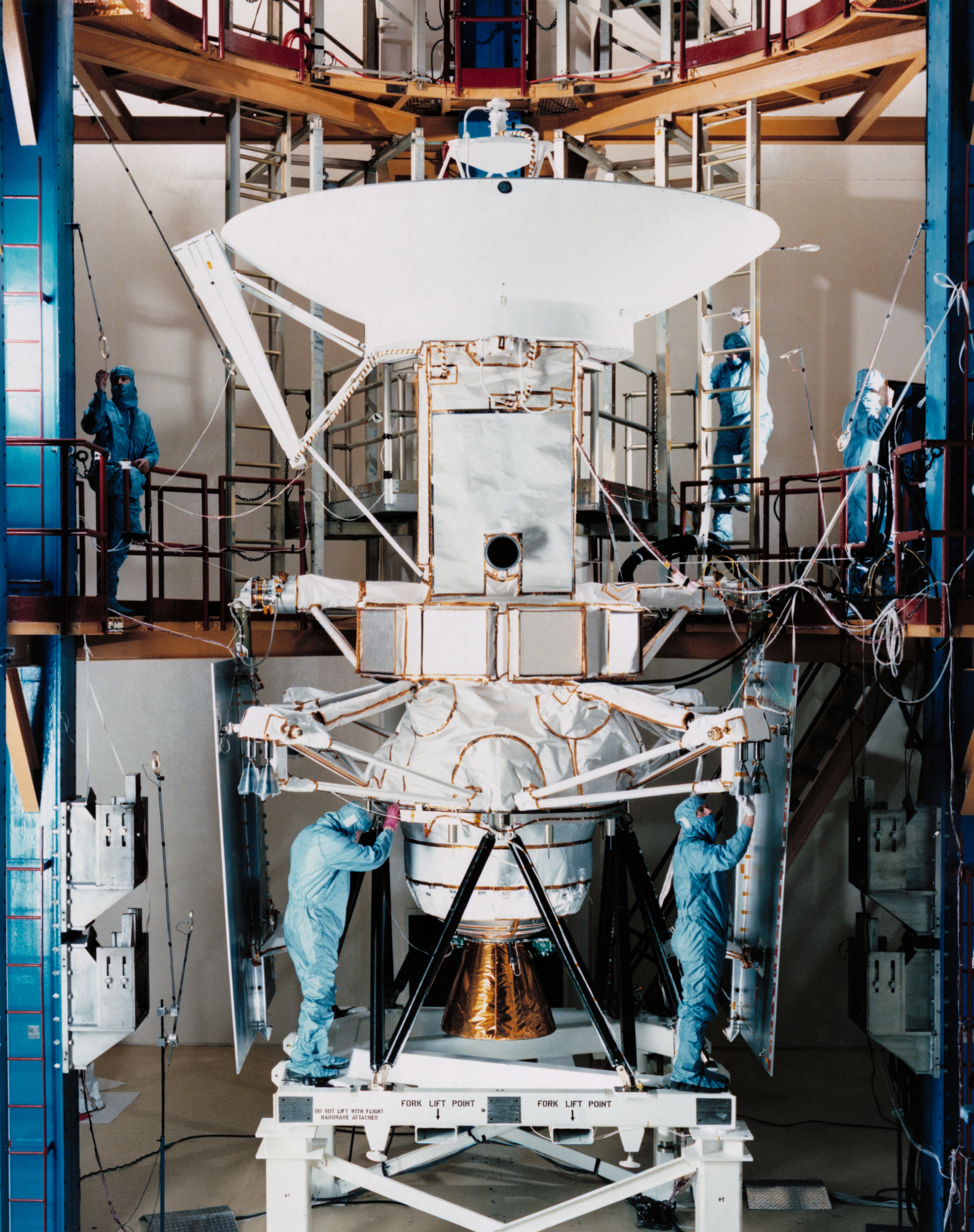
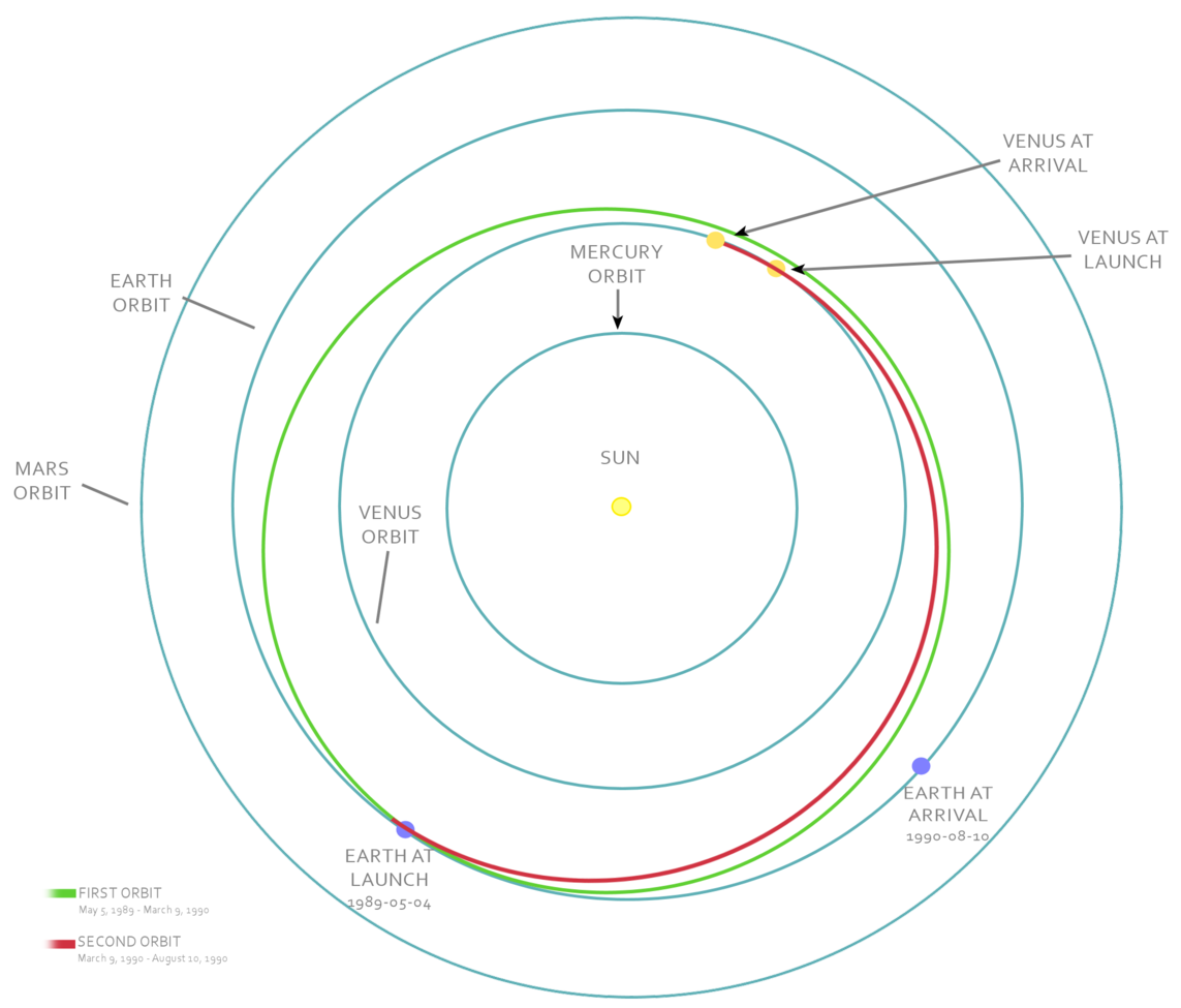
Left: Global map of Venus based on Pioneer Venus Orbiter radar data. Middle: Engineers at Martin Marietta prepare Magellan for shipment to NASA’s Kennedy Space Center in Florida. Right: Schematic of Magellan’s trajectory from Earth to Venus.
Magellan sought to acquire the highest resolution radar imagery of Venus, improving on data obtained by earlier spacecraft. During its 14 years orbiting Venus between 1978 and 1992, Pioneer Venus Orbiter, managed by the NASA Ames Research Center in California’s Silicon Valley, among other observations used its radar to map approximately 90% of Venus at a resolution of about 10 kilometers. Scientists yearned for higher resolution radar imagery, and the Soviet Union’s Venera 15 and 16, with their larger antennas, mapped about a quarter of the planet’s surface to a resolution of 1 to 2 kilometers between October 1983 and June 1984. Initiated as the Venus Radar Mapper mission in 1983, NASA renamed the project in 1985 after the 16th century Portuguese explorer Ferdinand Magellan. Martin Marietta Astronautics Group in Denver built the spacecraft, much of it from space parts, including using a spare main spacecraft bus from the Voyager program. Originally, plans called for Magellan to launch in April 1988 aboard the space shuttle using a Centaur upper stage to send it on a four-month journey to Venus. Following the Challenger accident, NASA canceled the Centaur as a space shuttle upper stage, remanifesting Magellan on the IUS. The first available launch window for a four-month flight occurred in October 1989, but the Jupiter-bound Galileo spacecraft needed that opportunity as it required a gravity-assist at Venus to get it to its final destination. Specialists settled on a longer flight time for Magellan to use the earlier April-May 1989 window. After deployment from the shuttle, the two-stage IUS would place Magellan on its interplanetary journey that would take it 1.5 times around the Sun. Arriving at Venus, Magellan’s solid-rocket Star 48B motor would fire to place it into orbit around Venus to begin its primary mission lasting 243 days, the duration of one Venusian day. Using its high-gain antenna as a radar dish, Magellan would map at least 70 percent of the cloud-shrouded planet’s surface to a resolution of one kilometer.
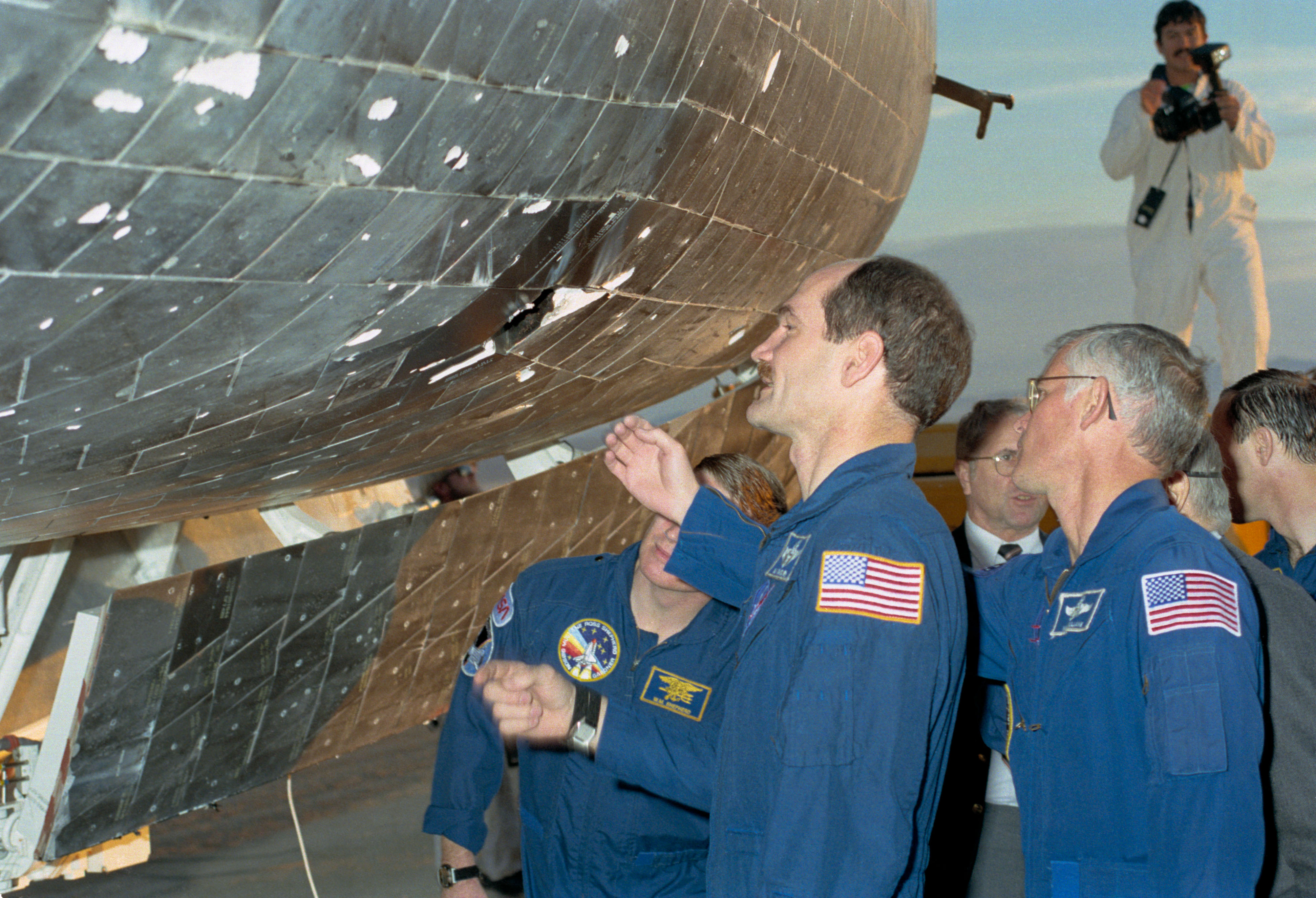
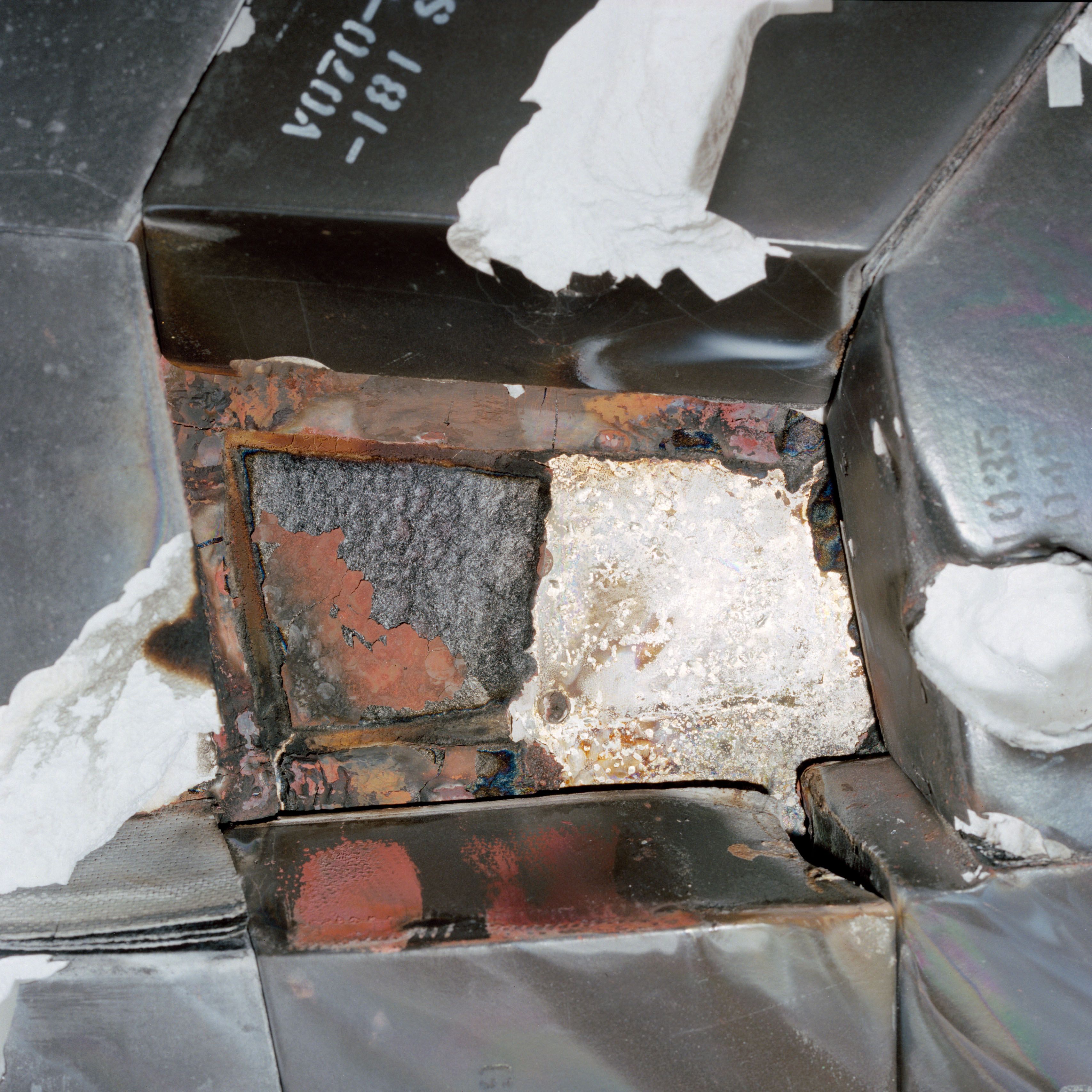
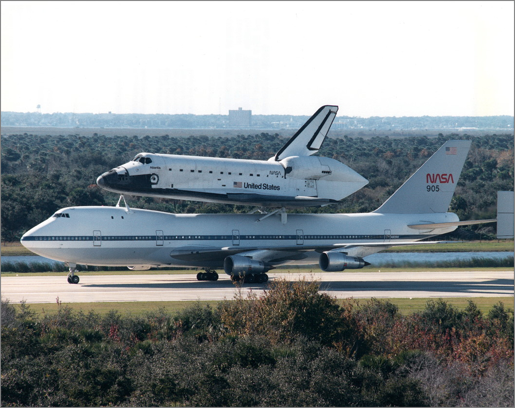
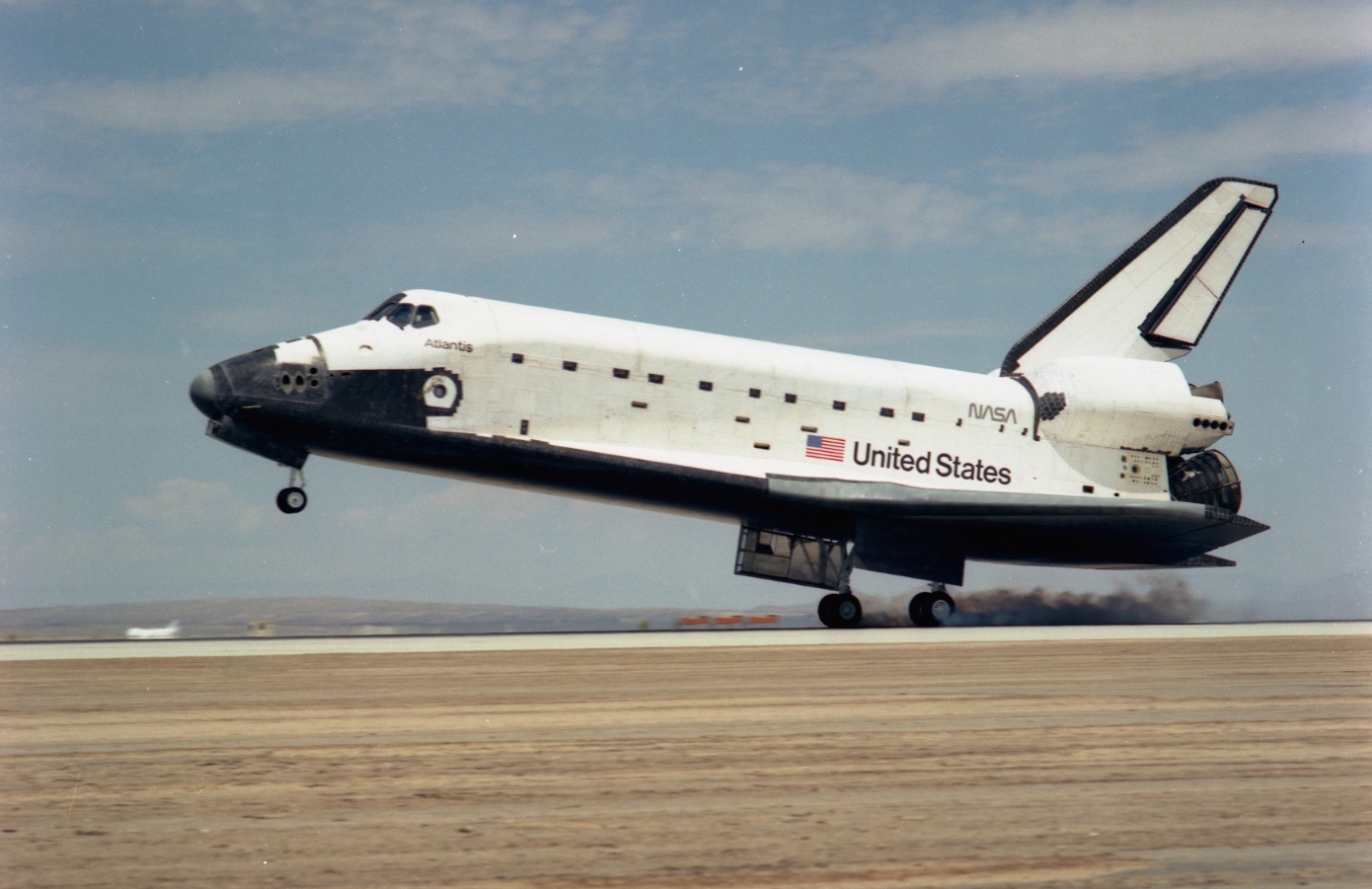
Left: STS-27 astronauts inspect the tile damage on Atlantis. Middle: Closeup of missing tile area on Atlantis. Right: Atlantis returns to NASA’s Kennedy Space Center in Florida following STS-27.
Atlantis landed at Edwards Air Force Base in California’s Mojave Desert on Dec. 6, 1988, concluding the STS-27 mission. During launch four days earlier, 85 seconds after liftoff a piece of insulation from the tip of the right-hand solid rocket booster broke away and struck Atlantis’ right side. While in orbit, the crew used the shuttle’s Remote Manipulator System, or robotic arm, to image Atlantis for any signs of damage. The astronauts clearly saw extensive damage on their onboard monitors, but due to the classified nature of the mission, downlinking the video required encryption that greatly degraded the image quality. Ground controllers did not fully appreciate the extent of the damage and remained unconcerned during Atlantis’ reentry. Not until the postlanding inspection did engineers and managers realize with alarm how close they came to disaster. Atlantis arrived back at KSC on Dec. 13, where workers towed it to the Orbiter Processing Facility (OPF) the next day for investigation into and repair of the most significant tile damage seen up to that time. More than 700 tiles received some damage, with one tile missing entirely and the underlying metal partially melted.
Left: Space shuttle Atlantis arrives at Launch Pad 39B. Middle: STS-30 astronauts pose with a model of Magellan following their March 27 preflight press conference. Right: Atlantis rises into the sky.
Magellan arrived at KSC on Oct. 8, 1988, for preflight processing in a clean room at the Spacecraft Assembly and Encapsulation Facility (SAFE). On Feb. 15, 1989, workers moved Magellan from the SAFE to the Vertical Processing Facility for mating with the IUS and reinstallation of its high-gain antenna. On March 17, they transported Magellan out to Launch Pad 39B, where it awaited Atlantis’ arrival.
On March 11, workers rolled Atlantis from the OPF to the Vehicle Assembly Building for mating with its External Tank and twin Solid Rocket Boosters. Atlantis rolled out to Launch Pad 39B on March 22, just nine days after Discovery lifted off from the same pad on the STS-29 mission, the shortest such turnaround time. Workers installed Magellan into Atlantis’ payload bay on March 25. The Terminal Countdown Demonstration Test took place on April 6-7, with the astronauts participating in the final few hours as on launch day. Senior NASA managers held the Flight Readiness Review on April 13-14 and declared Atlantis and Magellan ready for launch on April 28. The five-member astronaut crew arrived at KSC on April 25 for final preparations for the launch.
An international delegation including Soviet scientists and Soviet cosmonaut Igor D. Volk, training to fly the Soviet shuttle Buran, arrived at KSC to witness the planned launch. The countdown continued smoothly for the mid-afternoon liftoff until one of the range safety computers went offline. Faced with a short 23-minute launch window, range safety officers got the computer back online, having delayed the planned liftoff by only five minutes. Then at T-31 seconds, the ground launch sequencer called a halt to the countdown due to the failure of a recirculating pump in main engine number 1, scrubbing the launch for the day. The crew exited Atlantis 46 minutes later and returned to crew quarters to try another day. That day came on May 4, after technicians replaced the faulty pump and a hydrogen line. The launch window had grown to a more comfortable one hour and four minutes, with the fickle Florida weather using up much of that time.
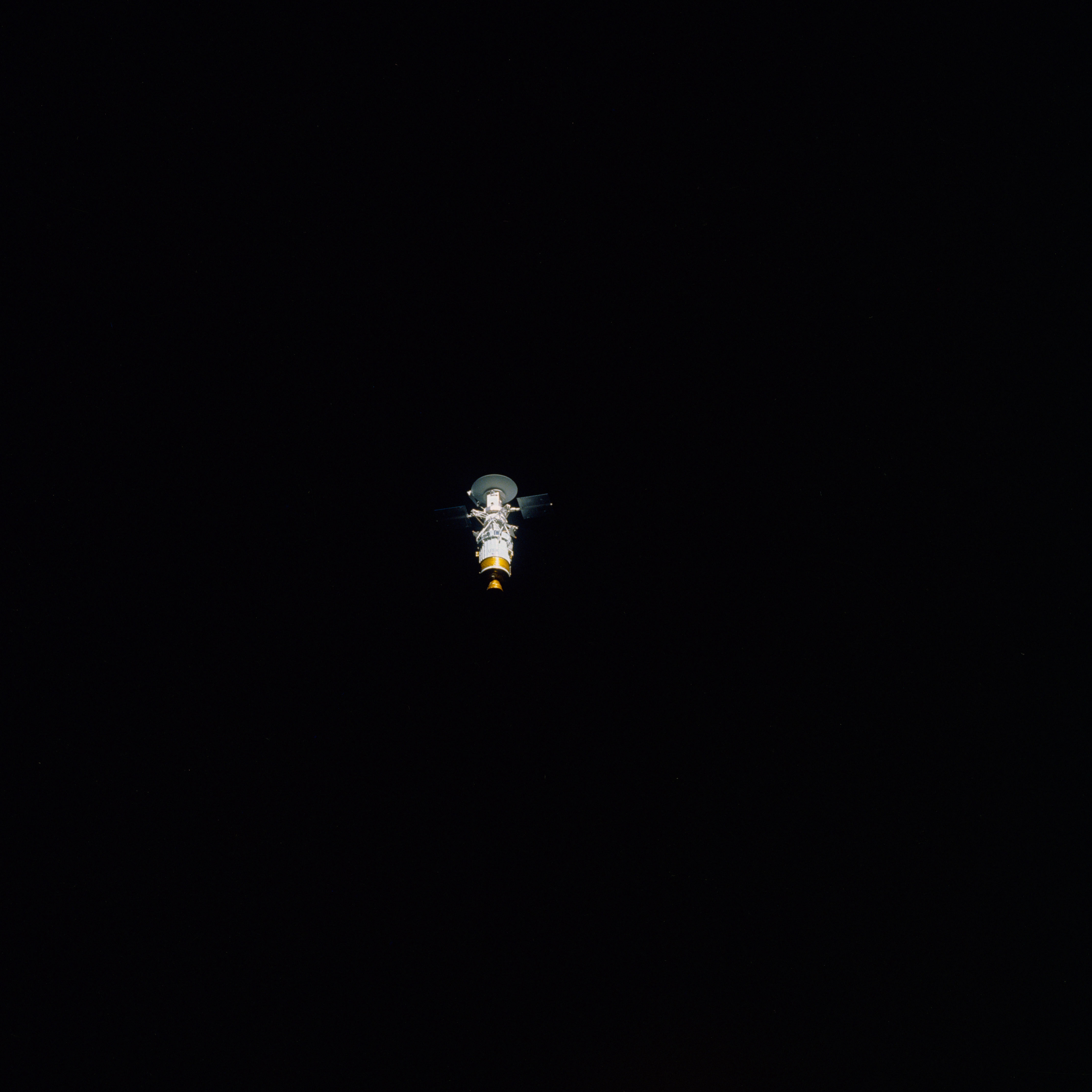
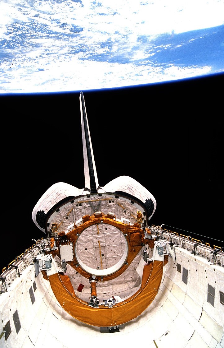
Left: Magellan in Atlantis’ payload bay, its large high-gain antenna prominently visible. Middle left: Magellan and its Inertial Upper Stage moments after deployment from Atlantis. Middle right: With its solar arrays now deployed, Magellan departs from the shuttle. Right: Atlantis’ empty payload bay after Magellan’s departure.
With clouds and winds threatening to scrub the launch, Atlantis found a few minutes of acceptable weather near the end of the launch window and lifted off at 2:47 p.m. EDT, sending America’s first planetary spacecraft in 11 years on a mission to map Venus’ cloud-shrouded surface. As soon as the shuttle cleared the launch tower, control shifted to the Mission Control Center at NASA’s Johnson Space Center in Houston, where Ascent Flight Director A. Lee Briscoe and his team of operators, including astronaut Frank L. Culbertson serving as the capsule communicator, or capcom, monitored all aspects of the launch. Following main engine cutoff, Atlantis and its crew had reached space but not yet achieved orbit. Two minutes later, a 2-minute 39-second firing of the Orbital Maneuvering System (OMS) engines placed them in a 184-by-75-mile orbit. Forty minutes later, a second 2-minute OMS burn circularized the orbit at 184 miles. The astronauts removed their bulky Launch and Entry Suits (LES) and prepared Atlantis for orbital operations, including opening the payload bay doors. Preparations for Magellan’s deployment began shortly thereafter. In Mission Control, Flight Director J. Milton Heflin and his team, including capcom Pierre J. Thuot, took over to assist the crew with deployment operations. The astronauts activated Magellan and the IUS and ground teams began checking out their systems, with the first TV from the mission showing the spacecraft and its upper stage in the payload bay. Walker and Grabe oriented Atlantis to the deployment attitude while Lee raised Magellan’s tilt table first to 29 degrees then to the deploy position of 52 degrees. With all systems operating normally, Mission Control gave the go for deploy. Six hours and 14 minutes into the mission, Walker called down, “Magellan is deployed.” The 40,118-pound spacecraft and upper stage combination glided over the shuttle’s crew compartment. Ten minutes later, Magellan deployed its two solar array wings to begin generating power. Walker and Grabe fired the two OMS engines to move Atlantis a safe distance away from the IUS burn that took place one hour after deployment, sending Magellan on its way to Venus. The primary task of the mission accomplished, the astronauts prepared for their first night’s sleep in space.
STS-30 crew Earth observation photographs. Left: The Texas Gulf Coast including Houston. Middle: New Orleans. Right: The Cape Canaveral area in Florida including NASA’s Kennedy Space Center.
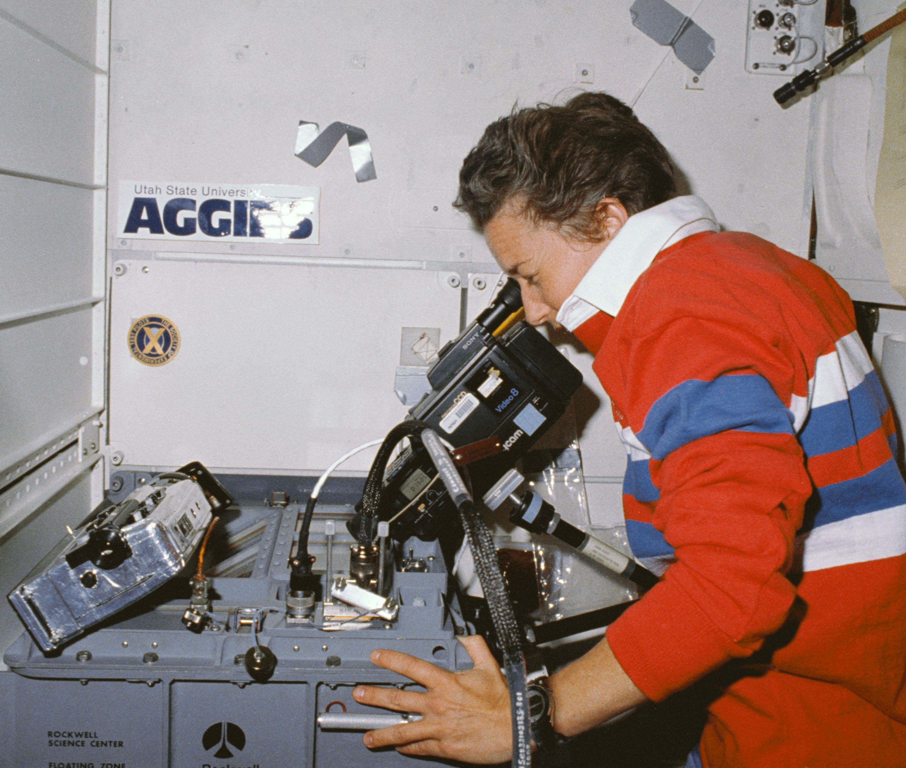
Mission Control awakened the crew with the theme music from the movie “Superman” to begin their second mission day, their first full day in space. Compared to their very busy first day, the rest of the mission’s timeline seemed relatively more relaxed. Cleave began work on the Fluids Experiment Apparatus (FEA), a modular chemistry and physics laboratory specifically designed for space shuttle missions. On STS-30, Cleave and Lee processed samples of indium and selenium in the FEA to see the effects of microgravity on the crystals produced. The astronauts took many photographs of the Earth as it passed by below them. Walker saluted the ground control teams at the Guam and Santiago, Chile, tracking stations, scheduled for closure at the end of STS-30. The deployment of the Tracking and Data Relay Satellite System made many ground stations obsolete.
To begin their third day in space, Mission Control awaked the astronauts with fight songs from their alma maters. The rousing music prompted Walker to say, “Good morning, Houston! Thanks for the great music!” After giving Mission Control a video tour of Atlantis’ cabin, Thagard and Lee began a test to see if the LES helmet with a Helmet Retention Assembly can serve to prebreathe pure oxygen prior to a spacewalk. With no spacewalk planned for STS-30, their test simply intended to prove the concept. After Thagard and Lee began to breathe pure oxygen, the crew lowered the cabin pressure from the nominal 14.7 pounds per square inch (psi) to 10.2 psi to assist in the prevention of decompression sickness, also known as the bends. After completing the one-hour test, Thagard and Lee removed their helmets.
Left: Mary L. Cleave videotapes the progress of an experiment in the Fluids Experiment Apparatus. Middle: Norman E. Thagard, left, and Mark C. Lee during the helmet retention assembly prebreathe test. Right: Inflight photograph of the STS-30 crew.
Mission Control began the astronaut’s fourth day in space, their last full day in orbit, with the theme music from the movie “Rocky.” The day’s first major event involved a 15-minute news conference with United Press International reporters Rob Navias and Bill Harwood. In preparation for the entry and landing the following day, the astronauts tested the vehicle’s Auxiliary Power Units, aerodynamic surfaces, and reaction control system thrusters. They then repressurized the cabin back to 14.7 psi. Suddenly, one of the spacecraft’s General Purpose Computers (GPC-4) went offline, failing to synchronize with the other GPCs. While not an immediate impact to their work, Mission Control was concerned about its function during the critical entry and landing the next day, and they ordered the crew to replace the faulty unit, never before done in space. The astronauts successfully completed the four-hour task and had the replacement GPC up and running, but the time spent on the computer replacement caused the cancellation of the final FEA sample run. The crew stayed up an extra hour to complete all their stowage tasks before retiring for their final night’s sleep in space.
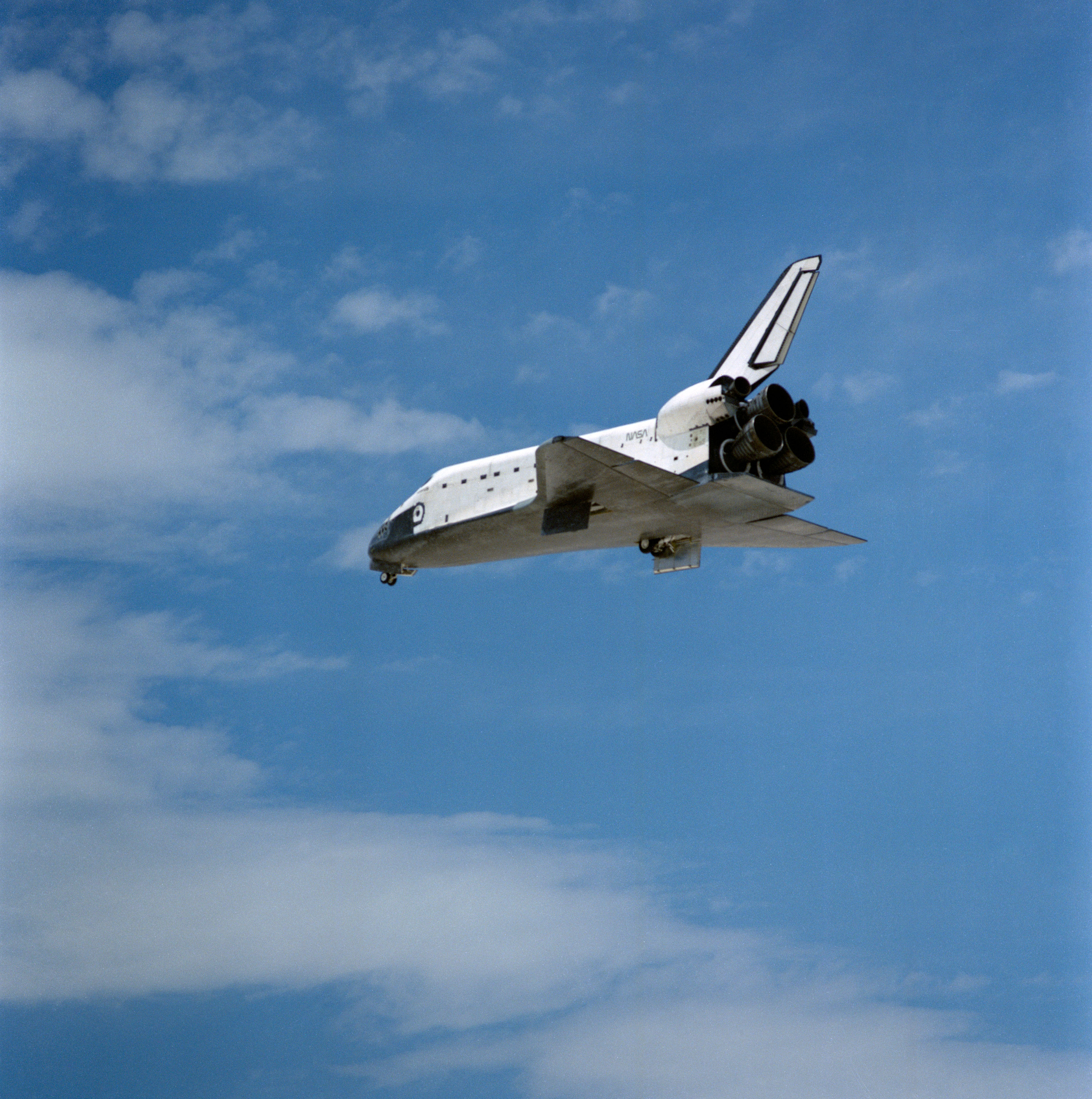
Left: Its landing gear lowered, Atlantis approaches the runway at Edwards Air Force Base in California. Middle: Atlantis touches down. Right: The STS-30 astronauts exit Atlantis.
On May 8, the astronauts awakened for their final day in space. The wake-up call from Mission Control consisted of a barking dog followed by The Beatles song “A Hard Day’s Night.” Capcom Kenneth D. Cameron greeted them with, “Good morning! It’s time to come home.” In preparation for reentry, the astronauts donned their orange LESs and closed the payload bay doors. Walker and Grabe oriented Atlantis into the deorbit attitude, with the OMS engines facing in the direction of travel. Over the Indian Ocean, they fired the two engines for 2 minutes 48 seconds to bring the spacecraft out of orbit. They reoriented the orbiter to fly with its heat shield exposed to the direction of flight as it encountered Earth’s atmosphere at 419,000 feet. The buildup of ionized gases caused by the heat of reentry prevented communications for about 15 minutes but provided the astronauts a great light show. Variable winds at Edwards Air Force Base in California complicated the decision on which runway to land on to complete a planned crosswind test. Mission Control decided to wait until 20 minutes before touchdown to make the final determination. With Atlantis out of the blackout, Mission Control directed the crew to land on concrete runway 22 with acceptable crosswinds for the test. After completing the 200-degree Heading Alignment Circle turn, Walker aligned Atlantis with the runway, and Grabe lowered the landing gear. Atlantis touched down and rolled to a stop, ending a 4-day 56-minute flight, having completed 65 orbits of the Earth.
A sample of Magellan radar images of Venus. Left: Three impact craters in Venus’ Lavinia Planitia. Middle: Volcano Sapas Mons. Right: Maat Mons, second highest peak on Venus.
After deployment from the space shuttle, Magellan began its interplanetary journey. Midcourse corrections on May 21, 1989, March 13, 1990, and July 25, 1990, refined the trajectory as Magellan completed its 15-month journey to Venus on Aug. 10, 1990, entering an elliptical near-polar orbit around the planet. Recovering from two early communications glitches, Magellan began returning high-quality radar images of the cloud-shrouded planet on Sept. 15. The spacecraft completed its primary 243-day (the time it took Venus to complete one rotation) mission on May 15, 1991, imaging 83.7 percent of the planet’s surface at a resolution of between 100 and 250 meters, surpassing the original mission goals. It completed five more 243-day cycles, ending on Oct. 13, 1994, finishing with a coverage of 98 percent of the planet. In the summer of 1993, controllers commanded Magellan to skim through Venus’ upper atmosphere and use aerobraking to circularize its orbit to allow detailed mapping of the planet’s gravity field. To gather more aerodynamic data, controllers commanded Magellan to plunge into the Venusian atmosphere on Oct. 13, 1994, and it burned up on entry, having completed one of the most successful interplanetary missions during 15,000 orbits of Venus. The spacecraft returned more data than all of NASA’s previous planetary missions combined.
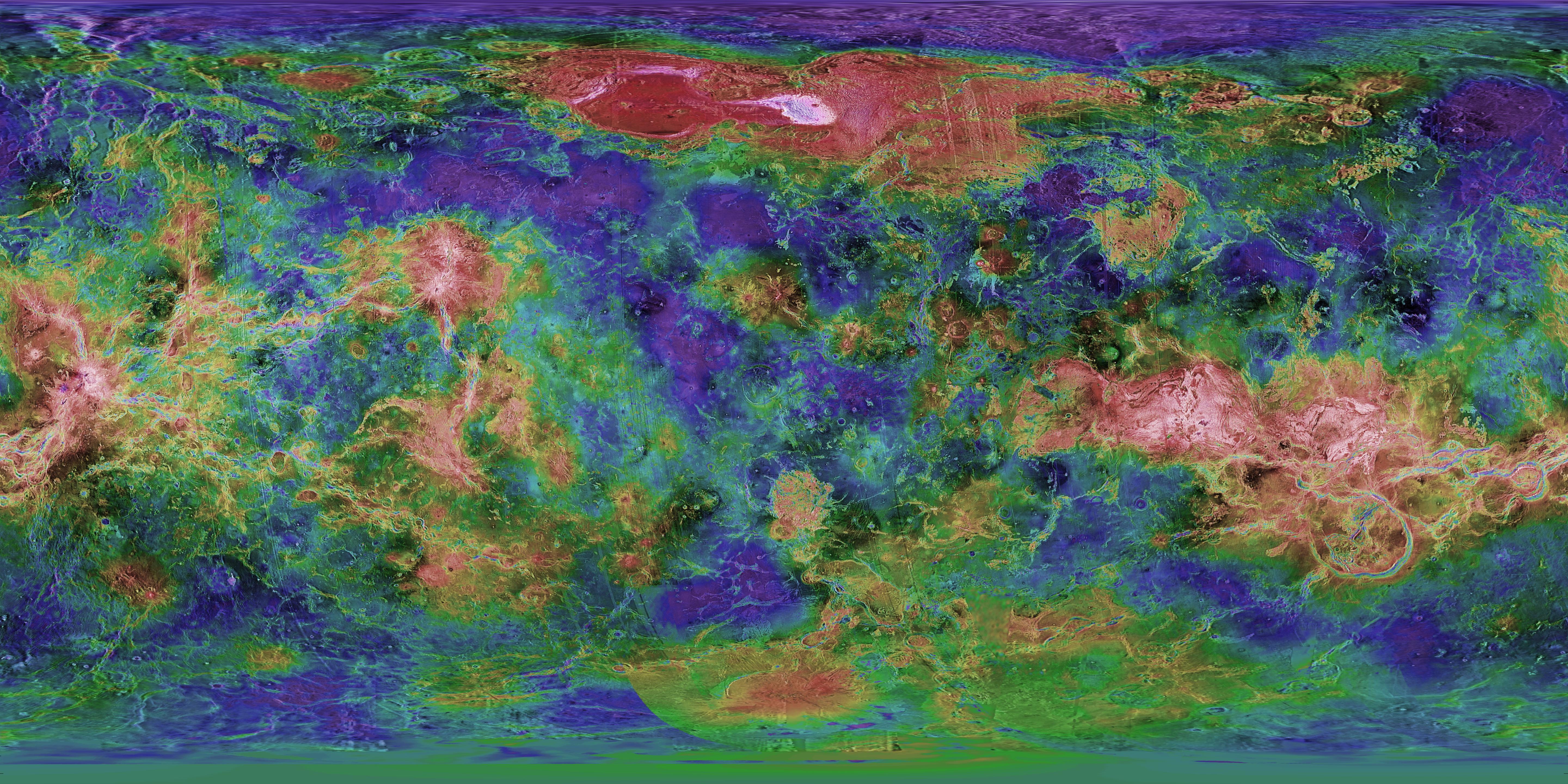
A topographic map of Venus based on Magellan radar data. Image credit: courtesy United States Geologic Service.
Radar data from Magellan allowed cartographers to create the first, and so far, the most detailed, global map of Venus. The images revealed a surface dominated by volcanic features with few impact craters, implying a geologically young surface, less than 800 million years old. Although Venus has a dense atmosphere, Magellan found little evidence of wind erosion, and the total absence of water makes erosion a very slow process on the planet.
Enjoy the crew narrated video of the STS-30 mission.
Read Cleave’s recollections of the STS-30 mission in her oral history with the JSC History Office.
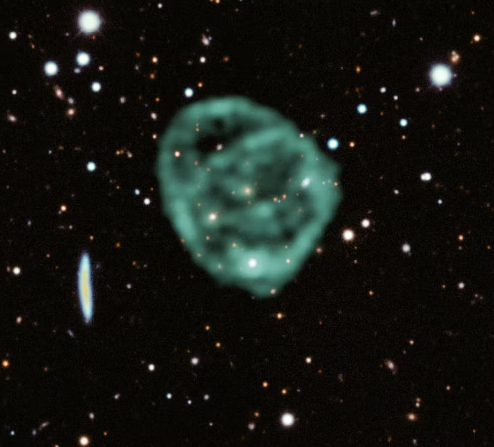
X-ray Satellite XMM-Newton Sees ‘Space Clover’ in a New Light
Astronomers have discovered enormous circular radio features of unknown origin around some galaxies. Now, new observations of one dubbed the Cloverleaf suggest it was created by clashing groups of galaxies.
Studying these structures, collectively called ORCs (odd radio circles), in a different kind of light offered scientists a chance to probe everything from supersonic shock waves to black hole behavior.
“This is the first time anyone has seen X-ray emission associated with an ORC,” said Esra Bulbul, an astrophysicist at the Max Planck Institute for Extraterrestrial Physics in Garching, Germany, who led the study. “It was the missing key to unlock the secret of the Cloverleaf’s formation.”
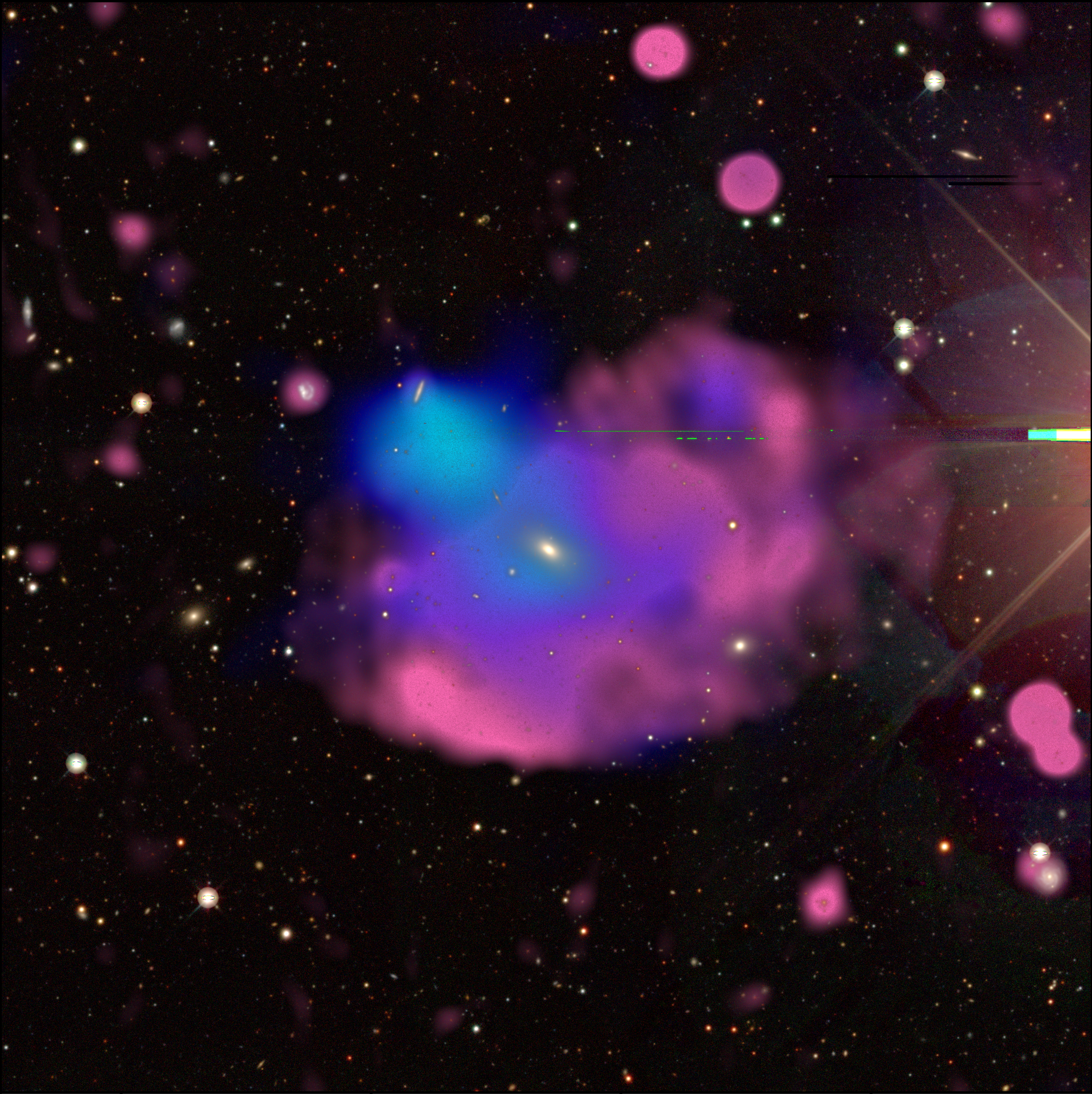
This multiwavelength image of the Cloverleaf ORC (odd radio circle) combines visible light observations from the DESI (Dark Energy Spectroscopic Instrument) Legacy Survey in white and yellow, X-rays from XMM-Newton in blue, and radio from ASKAP (the Australian Square Kilometer Array Pathfinder) in red.
X. Zhang and M. Kluge (MPE), B. Koribalski (CSIRO)
A Serendipitous Discovery
Until 2021, no one knew ORCs existed. Thanks to improved technology, radio surveys became sensitive enough to pick up such faint signals. Over the course of a few years, astronomers discovered eight of these strange structures scattered randomly beyond our galaxy. Each is large enough to envelop an entire galaxy –– sometimes several.
“The power needed to produce such an expansive radio emission is very strong,” Bulbul said. “Some simulations can reproduce their shapes but not their intensity. No simulations explain how to create ORCs.”
When Bulbul learned ORCs hadn’t been studied in X-ray light, she and postdoctoral researcher Xiaoyuan Zhang began poring over data from eROSITA (Extended Roentgen Survey with an Imaging Telescope Array), an orbiting German/Russian X-ray telescope. They noticed some X-ray emission that seemed like it could be from the Cloverleaf, based on less than 7 minutes of observation time.
That gave them a strong enough case to assemble a larger team and secure additional telescope time with XMM-Newton, an ESA (European Space Agency) mission with NASA contributions.
“We were allotted about five-and-a-half hours, and the data came in late one evening in November,” Bulbul said. “I forwarded it to Xiaoyuan, and he came into my office the next morning and said, ‘Detection,’ and I just started cheering!”
“We really got lucky,” Zhang said. “We saw several plausible X-ray point sources close to the ORC in eROSITA observations, but not the expanded emission we saw with XMM-Newton. It turns out the eROSITA sources couldn’t have been from the Cloverleaf, but it was compelling enough to get us to take a closer look.”
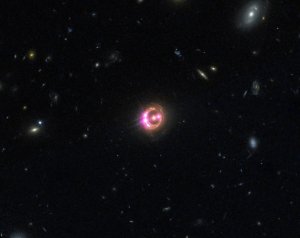
This image of the first ORC (odd radio circle) ever discovered, aptly dubbed ORC-1, overlays radio observations from South Africa’s MeerKAT telescope in green atop an optical and infrared map from the international DES (Dark Energy Survey) project.
J. English (U. Manitoba)/EMU/MeerKAT/DES (CTIO)
Gallivanting Galaxies
The X-ray emission traces the distribution of gas within the group of galaxies like police tape around a crime scene. By seeing how that gas has been disturbed, scientists determined that galaxies embedded in the Cloverleaf are actually members of two separate groups that drew close enough together to merge. The emission’s temperature also hints at the number of galaxies involved.
When galaxies join, their higher combined mass increases their gravity. Surrounding gas begins to fall inward, which heats up the infalling gas. The greater the system’s mass, the hotter the gas becomes.
Based on the emission’s X-ray spectrum, it’s around 15 million degrees Fahrenheit, or between 8 and 9 million degrees Celsius. “That measurement let us deduce that the Cloverleaf ORC is hosted by around a dozen galaxies that have gravitated together, which agrees with what we see in deep visible light images,” Zhang said.
The team proposes the merger produced shock waves that accelerated particles to create radio emission.
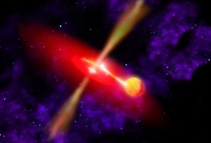
“Galaxies interact and coalesce all the time,” said Kim Weaver, the NASA project scientist for XMM-Newton at NASA’s Goddard Space Flight Center in Greenbelt, Maryland, who was not involved in the study. “But the source of the accelerated particles is unclear. One fascinating idea for the powerful radio signal is that the resident supermassive black holes went through episodes of extreme activity in the past, and relic electrons from that ancient activity were reaccelerated by this merging event.”
While galaxy group mergers are common, ORCs are very rare. And it’s still unclear how these interactions can produce such strong radio emissions.
“Mergers make up the backbone of structure formation, but there’s something special in this system that rockets the radio emission,” Bulbul said. “We can’t tell right now what it is, so we need more and deeper data from both radio and X-ray telescopes.”
The team solved the mystery of the nature of the Cloverleaf ORC, but also opened up additional questions. They plan to study the Cloverleaf in more detail to tease out answers.
“We stand to learn a lot from more thorough observations because these interactions take in all kinds of science,” Weaver says. “You’ve pretty much got everything that we deal with in the cosmos put together in this little package. It’s like a mini universe.”
For more information on ESA’s XMM-Newton mission, visit:
Marshall Prepares for Strategic Facilities Updates
NASA’s Marshall Space Flight Center is getting ready for the next big step in the evolution of its main campus. Through a series of multi-year infrastructure projects, Marshall is optimizing its footprint to assure its place as a vibrant and vital hub for the aerospace community in the next era.
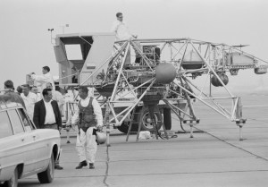
Near-term plans call for the carefully orchestrated take-down of 19 obsolete and idle structures – among them the 363-foot-tall Dynamic Test Stand, the Propulsion and Structural Test Facility, and Neutral Buoyancy Simulator. These facilities are not required for current or future missions, and the demolitions will help the center transition to a more modern, sustainable, and affordable infrastructure.
Test engineers fire up the Saturn I rocket’s first stage (S-1-10) at the Propulsion and Structural Test Facility, or “T-tower,” at NASA’s Marshall Space Flight Center in 1964.
NASA
“These facilities helped NASA make history – the Dynamic Test Stand was the tallest manmade structure in North Alabama and helped us test both the Saturn V rocket and the space shuttle,” said Joseph Pelfrey, Marshall’s center director. “Without these structures, we wouldn’t have the space program we have today. While it is hard to let them go, the most important legacy remaining are the people that built and stewarded these facilities and the missions they enabled. That same bold spirit fuels us, today. We are committed to carrying it forward to inspire the workforce of tomorrow.”
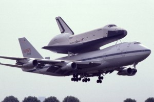
Built in 1964, the Dynamic Test Stand initially was used to test fully assembled Saturn V rockets. In 1978, engineers there also integrated all space shuttle elements for the first time, including the orbiter, external fuel tank, and solid rocket boosters.
The Propulsion and Structural Test Facility – better known at Marshall as the “T-tower” due to its unique shape – was built in 1957 by the U.S. Army Ballistic Missile Agency and transferred to NASA when Marshall was founded in 1960. There, engineers tested components of the Saturn launch vehicles, the Army’s Redstone Rocket, and shuttle solid rocket boosters.
The Neutral Buoyancy Simulator, including its 1.3-million-gallon tank and control room, was built in the late 1960s. From 1969 until its closing in 1997, the facility enabled NASA astronauts and researchers to experience near-weightlessness, conducting underwater testing of space hardware and practice runs for servicing the Hubble Space Telescope. It was replaced in 1997 by a new facility at NASA’s Johnson Space Center.
Astronauts conduct underwater testing on the International Space Station’s power module in the Neutral Buoyancy Simulator at Marshall in 1995.
NASA
Honoring the Past, Building the Future
Marshall master planner Justin Taylor said the facilities team looked at every possibility for refurbishing the old sites.
“The upkeep of aging facilities is costly, and we have to put our funding where it does the most good for NASA’s mission,” he said. “These are tough choices, but we have to prioritize function and cost over nostalgia. We’re making way for what’s next.”
To preserve NASA history, the agency has worked with architectural historians over the years on detailed drawings, written histories, and large-format photographs of the sites. Those documents are part of the Library of Congress’s permanent Historic American Engineering Record collection, making their history and accomplishments available to the public for generations to come.
Marshall facilities engineers are still finalizing the details and timeline for the demolitions. Work is expected to begin in late 2024 and end in late 2025. Additionally, to support the center’s employees and all the mission work they are doing, Marshall has a few infrastructure projects in design stages that will include the construction of two state-of-the-art buildings within the decade ahead.
A new Marshall Exploration Facility will offer a two to three story facility at approximately 55,000 square feet located within the 4200 complex. The facility will include an auditorium, along with conferencing, training, retail, and administrative spaces. The new Engineering Science Lab – at approximately 140,000 square feet – will provide a modern, flexible laboratory environment to accommodate a new focus for research and testing capabilities.
Ultimately, NASA’s vision for Marshall is a dynamic, interconnected campus. The center’s master plan features a central greenway connecting its two most densely populated zones – its administrative complex and engineering complex.
“As we look towards the aspirational goals we have as an agency, Marshall’s contributions may look different than our past but be no less important,” said Pelfrey. “And we want our partners, employees, and the community to be part of the evolution with us, bringing complementary skills and capabilities, innovative ideas, and a passion for exploration and discovery.”
Center Helps Grow Team Redstone’s Green Canopy for Earth Day
Redstone Arsenal and Marshall Space Flight Center leaders stand beside a carefully selected Ginkgo tree during Earth Day activities April 25 at Marshall’s food truck corral. The “Autumn Gold” Ginkgo will grow behind the Medical Center at Building 4249 as a living reminder of Marshall’s commitment to sustainability and environmental stewardship. From left, Redstone Arsenal Garrison Commander Col. Brian Cozine; Deputy Garrison Commander Martin Traylor; Deputy Director of Marshall’s Office of Center Operations Bill Marks; Environmental Engineering and Occupational Health Manager Farley Davis; Director of Center Operations June Malone; and Associate Center Director, Technical, Larry Leopard.
NASA/Charles Beason
Earth Day volunteers Sahana Parker, center, and Jacob Jolley, right, help hand out hundreds of saplings April 25 in a tree giveaway organized by Marshall’s Environmental Engineering and Occupational Health Office and Green Team.
NASA/Charles Beason
Environmental Protection Specialist Joni Melson, right, lends a helping hand to a fellow plant lover at Marshall’s Earth Day celebration April 25. Melson led Marshall’s planning and coordination for the event, a joint effort with Team Redstone.
Michoud Workforce ‘Goes Green’ in Celebration of Earth Day
Team members at NASA’s Michoud Assembly Facility marked Earth Day 2024 on April 22 by planting satsuma trees and small plants near administrative and office buildings.
From left, Boeing Michoud Deputy Site Leader Brad Saxton, Michoud Assembly Facility Director Hansel Gill, Textron Supervisor Inventory Control/Shipping MAF/Stone Road Wendy Dedeaux, Lockheed Martin Environmental Health and Safety Engineer Darrell Christian, Michoud Environmental Officer Ben Ferrell, and Syncom Space Services Environmental Manager Eric Stack pack in dirt and mulch around a newly planted satsuma tree at Michoud.
NASA/Steven Seipel
Nearly 50 employees from NASA, Boeing, Lockheed Martin, Syncom Space Services (S3), Textron, and various other contractors worked together to weed flower beds and pick up litter and debris around the 829-acre site on Earth Day.
“The Earth Day activities this morning were not only good for the environment, but also good for our workforce,” said Michoud Director Hansel Gill, “It was a pleasure to see folks from various contractors and tenants come together, get their hands dirty, and enjoy the comradery. Everyone was smiling, the weather was perfect, morale was high, and we look forward to hosting more opportunities such as this in the future.”
Earth Day-Tree Planting and Building 101/102 Alley Clean Up
NASA/Steven Seipel
Crystal Farmer, left, and Jennifer York of Boeing show off “MAF Goes Green” giveaways handed out during the April 22 cleanup activities.
NASA/Steven Seipel
Earth Day-Tree Planting and Building 101/102 Alley Clean Up
NASA/Steven Seipel
NASA’s Michoud Assembly Facility team members join in cleanup and beautification efforts at Michoud in celebration of Earth Day 2024.
Export Control Office Keeps Marshall Safe and Secure When Sharing Knowledge
By Jessica Barnett
As a team member at NASA’s Marshall Space Flight Center, it’s your responsibility to help make sure information doesn’t fall into the wrong hands. That includes checking in with the center’s Export Control Office before a presentation or visit with foreign nationals or entities.
Marshall’s Export Control Program features four staff members and a multitude of certified Center Export Representatives (CERs) who will work with team members to ensure organizations can get their work done without violating export control laws.
Marshall Space Flight Center’s Export Control Program team includes, from left, Elizabeth Ewald, senior export compliance specialist; Sean Benson, center export administrator; Chris Jones, export compliance specialist; and Chris Mathews, assistant center export administrator.
NASA/Jessica Barnett
“We’re a service organization with a mission to help NASA employees navigate the very complex world of export controls,” said Sean Benson, who serves as Marshall’s center export administrator. “They’re laws that all U.S. entities – government included – must follow. Our role is to help the exporter navigate those in an efficient and compliant way.”
It’s important to note that exports aren’t just physical goods being shipped overseas. They can include items shared virtually with foreign companies, visits from foreign nationals, presentations with non-U.S. schools or universities, and more.
“I often get asked to review presentations for export control content,” said Elizabeth Ewald, senior export compliance specialist at Marshall. “I also help with international shipping.”
“We review if NASA’s going to be disposing of property, selling it out to markets. We make sure that if it’s going, it’s going to the proper parties,” Benson said. “We also do a lot of work with foreign national visits. We do risk assessment for every foreign national visit that comes from Marshall Space Flight Center, including Michoud Assembly Facility and the National Space Science Technology Center.”
CERs play an important role in the process. Benson and Ewald advise each technical organization at Marshall to have at least one CER.
“They’re our eyes, ears, hands, and feet on the ground within the individual areas of the center,” Ewald said. “They speak engineering, and we don’t; we speak export, and they don’t. Together, we make a great team to help when reviewing papers, presentations, and what-have-you.”
To become a CER, a team member must complete 10 prerequisite courses in SATERN, then complete two live Teams sessions, which are four hours each. Once certified, they’ll need to complete annual recertification to remain on the office’s active CERs list.
One of the export control team’s many roles at Marshall is reviewing presentations, images, and other information that might be shared virtually with foreign nationals or entities.
NASA/Jessica Barnett
That list is just one of the many tools available for team members who visit the office’s SharePoint page on Inside Marshall. The page also features contact information for the office’s staff members, ways to file a request for export authorization or policy review, and access to the International Traffic in Arms Regulations (ITAR) and Export Administration Regulations (EAR), which are the two rulebooks that govern the Export Control Program.
“You can request training, too,” Benson said. “You can also see our reference materials, including some helpful job aids for things like marking Controlled Unclassified Information (CUI) documents.”
Each NASA center has its own Export Control Program to match that center’s focus. Benson said he’s proud to work at Marshall, where – in the words of Center Director Joseph Pelfrey – he can work on a rocket that’s going to the Moon in the morning and on a rocket that’s coming back from Mars in the afternoon.
“The best part of my job is being involved with helping programs and projects work with their national partners to do cool stuff in space,” Benson said. “I never thought that I would be involved in things like helping people get satellites from one place to another and safely to a launchpad.”
“We’re here to help,” Ewald said. “We want you guys to be able to do what you want to do, so get us involved. Sometimes the things we need to help you with will take more than 90 days to accomplish, so the sooner you get us involved, the better.”
Team members can learn more about Marshall’s Export Control Office by visiting its SharePoint page on Inside Marshall. Organizations can also reach out to the office to request a training or presentation tailored to that organization’s specific export control needs.
Barnett, a Media Fusion employee, supports the Marshall Office of Communications.
Marshall’s Energy and Water Team Wins Federal Energy Management Program Award
By Celine Smith
It’s easy to see the green pastures and rolling hills surrounding NASA’s Marshall Space Flight Center on Redstone Arsenal and think of them as untouched.
In reality, the energy and water team within Marshall’s Center of Operations Office takes great care in managing the sustainable use of the environment. Not only does their work benefit the environment, but their commitment to decrease the usage of water and energy can save taxpayer’s money. The team was recently rewarded for their efforts, earning an award March 27 from the Federal Energy Management Program for their project: water leak detection and advanced metering infrastructure.
This landscape of “mountains” and “valleys” speckled with glittering stars is actually the edge of a nearby, young, star-forming region called NGC 3324 in the Carina Nebula. Captured in infrared light by NASA’s new James Webb Space Telescope, this image reveals for the first time previously invisible areas of star birth.
NASA/FEMP
“I love saving energy and money for the taxpayer,” said Rhonda Truitt, the energy and water manager for Marshall. “I also feel like it’s the right thing to do as a good steward of our planet and for our community.”
The team ensures the center meets and exceeds federal expectations of efficient usage of energy and water. With this objective in mind, it implements innovative methods to conserve resources. The energy and water team partnered with the Army and Huntsville Utilities for the two projects.
For the water leak detection project, a team comprised of Truitt, Marshall’s Operation & Maintenance, and the SMART center initiative, placed acoustic sensors mimicking hydrant caps on hydrants across Marshall. The sensor monitors irregular sounds that indicate a leak and identifies its approximate location, decreasing the time needed in what was previously an hours-long process to find leaks.
Truitt said the technology has more benefits other than saving money. Fixing leaks prevents clean water from being contaminated by historical industrial operations and flowing into natural water resources like the Tennessee River. Leaks can also cause sinkholes that could endanger team members and buildings, so discovering them early is important.
From left, Thaller, Truitt, and Bertrand together at the FEMP award ceremony.
NASA/FEMP
For example, the team discovered three leaks the first day the project was put into place. A hole causing one leak measured at one-sixteenth of an inch and was leaking 900 gallons of water a day. The sensors have led to four leaks being repaired, with about $10,000 saved for each.
“Small things can make a difference,” Truitt said. “With the number of employees at Marshall, small actions like allowing a leak or drip to go unreported can add up.”
The advanced metering infrastructure works together with water leak detection by calculating how much water used across the center. The energy and water team can ensure Marshall is accurately charged for water and keep track of overall water usage. The success of the two projects won’t only benefit Huntsville. According to Truitt, federal sites across the U.S. could adopt these methods, leading to water and money savings nationwide.
“My role doesn’t only make a difference financially, I get to support NASA’s missions while sustaining and protecting the world we live in,” Truitt said. “It’s really cool to feel like you make short-term and long-term differences.”
Smith,a Media Fusion employee, supports the Marshall Office of Communications.
Michoud All-Hands Provides Updates, Introductions to New Leadership and Initiatives
NASA’s Michoud Assembly Facility Director Hansel Gill held a Michoud All-Hands meeting for facility team members April 24.
NASA’s Michoud Assembly Facility Director Hansel Gill speaks to attendees during his first Michoud All-Hands since being named director in early April.
NASA/Michael DeMocker
The meeting was the first formal all-hands for Gill since officially taking on his new role earlier in the month.
Michoud civil servants and direct support employees attend the facility’s all-hands meeting April 24, getting updates on topics including hardware production, infrastructure, and NASA 2040.
NASA/Michael DeMocker
Michoud civil servants and direct support employees attended the event, which included updates on hardware production and infrastructure improvements and repairs, as well as discussions on Michoud’s culture.
MAF Ambassadors Ben Ferrell, Jesse Lemonte, and Kevin Stiede address attendees on NASA 2040 and other Marshall Space Flight Center’s Center Action Team initiatives.
NASA/Michael DeMocker
Gill then introduced the “MAF Ambassadors” from NASA Marshall Space Flight Center’s Center Action Team to speak on NASA 2040 and other future initiatives before opening the floor to questions.
NASA’s Optical Comms Demo Transmits Data Over 140 Million Miles
Riding aboard NASA’s Psyche spacecraft, the agency’s Deep Space Optical Communications technology demonstration continues to break records. While the asteroid-bound spacecraft doesn’t rely on optical communications to send data, the new technology has proven that it’s up to the task. After interfacing with the Psyche’s radio frequency transmitter, the laser communications demo sent a copy of engineering data from over 140 million miles away, 1½ times the distance between Earth and the Sun.
This achievement provides a glimpse into how spacecraft could use optical communications in the future, enabling higher-data-rate communications of complex scientific information as well as high-definition imagery and video in support of humanity’s next giant leap: sending humans to Mars.
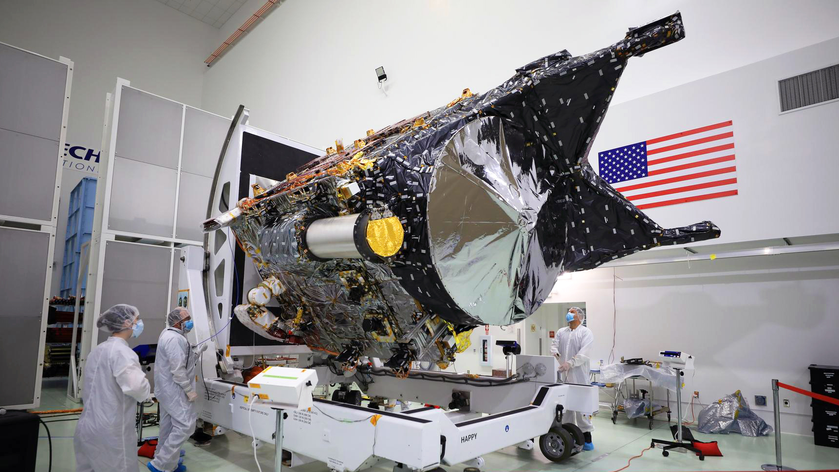
NASA’s Psyche spacecraft is shown in a clean room at the Astrotech Space Operations facility near the agency’s Kennedy Space Center on Dec. 8, 2022. The optical communications gold-capped flight laser transceiver can be seen, near center, attached to the spacecraft.
NASA/Ben Smegelsky
“We downlinked about 10 minutes of duplicated spacecraft data during a pass on April 8,” said Meera Srinivasan, the project’s operations lead at NASA’s Jet Propulsion Laboratory. “Until then, we’d been sending test and diagnostic data in our downlinks from Psyche. This represents a significant milestone for the project by showing how optical communications can interface with a spacecraft’s radio frequency comms system.”
The laser communications technology in this demo is designed to transmit data from deep space at rates 10 to 100 times faster than the state-of-the-art radio frequency systems used by deep space missions today.
After launching on Oct. 13, 2023, the spacecraft remains healthy and stable as it journeys to the main asteroid belt between Mars and Jupiter to visit the asteroid Psyche.
NASA’s optical communications demonstration has shown that it can transmit test data at a maximum rate of 267 megabits per second (Mbps) from the flight laser transceiver’s near-infrared downlink laser – a bit rate comparable to broadband internet download speeds.
That was achieved on Dec. 11, 2023, when the experiment beamed a 15-second ultra-high-definition video to Earth from 19 million miles away (31 million kilometers, or about 80 times the Earth-Moon distance). The video, along with other test data, including digital versions of Arizona State University’s Psyche Inspired artwork, had been loaded onto the flight laser transceiver before Psyche launched last year.
Now that the spacecraft is more than seven times farther away, the rate at which it can send and receive data is reduced, as expected. During the April 8 test, the spacecraft transmitted test data at a maximum rate of 25 Mbps, which far surpasses the project’s goal of proving at least 1 Mbps was possible at that distance.
The project team also commanded the transceiver to transmit Psyche-generated data optically. While Psyche was transmitting data over its radio frequency channel to NASA’s Deep Space Network (DSN), the optical communications system simultaneously transmitted a portion of the same data to the Hale Telescope at Caltech’s Palomar Observatory in San Diego County, California – the tech demo’s primary downlink ground station.
“After receiving the data from the DSN and Palomar, we verified the optically downlinked data at JPL,” said Ken Andrews, project flight operations lead at JPL. “It was a small amount of data downlinked over a short time frame, but the fact we’re doing this now has surpassed all of our expectations.”
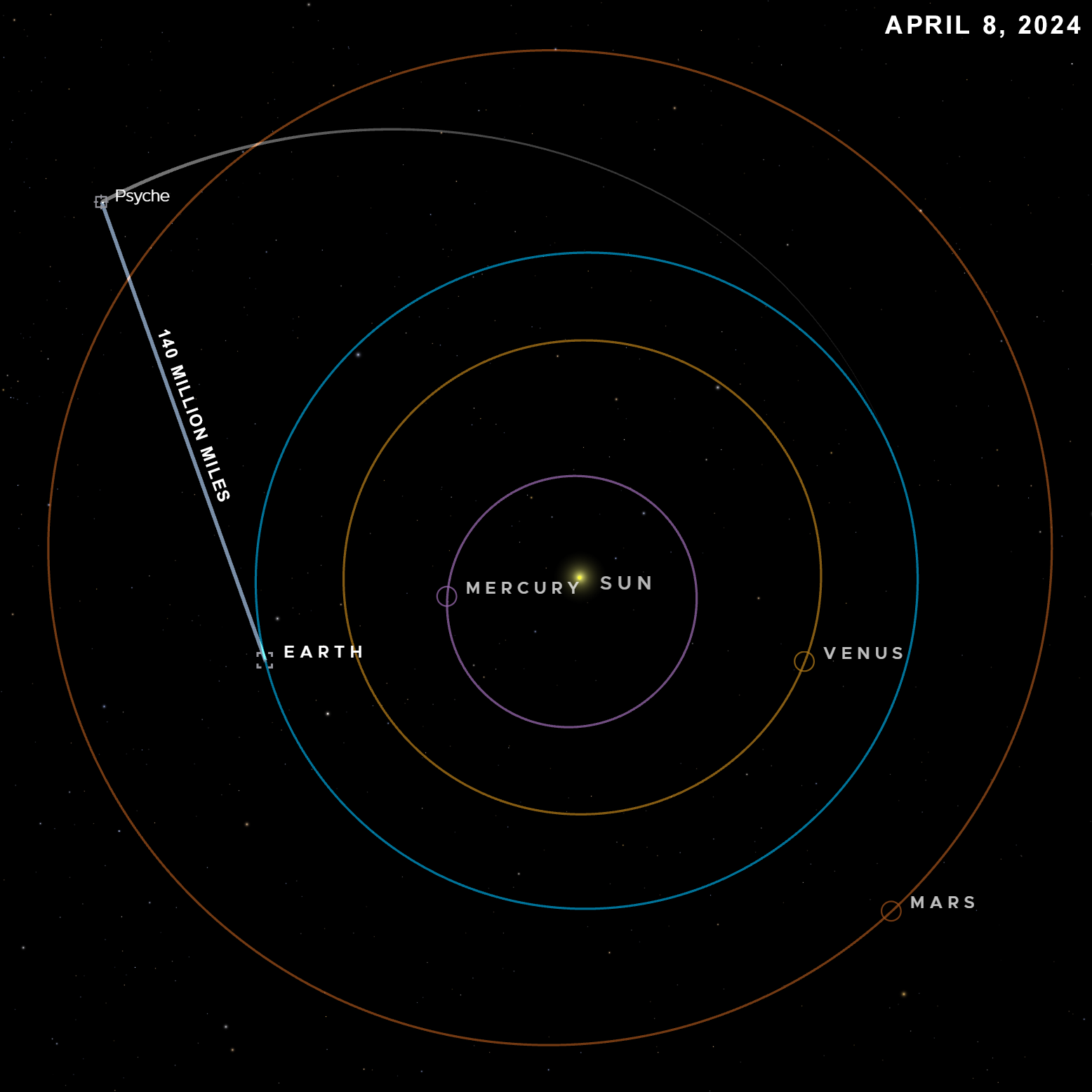
This visualization shows the Psyche spacecraft’s position on April 8 when the optical communications flight laser transceiver transmitted data at a rate of 25 Mbps over 140 million miles to a downlink station on Earth.
NASA/JPL-Caltech
After Psyche launched, the optical communications demo was initially used to downlink pre-loaded data, including the Taters the cat video. Since then, the project has proven that the transceiver can receive data from the high-power uplink laser at JPL’s Table Mountain facility, near Wrightwood, California. Data can even be sent to the transceiver and then downlinked back to Earth on the same night, as the project proved in a recent “turnaround experiment.”
This experiment relayed test data – as well as digital pet photographs – to Psyche and back again, a round trip of up to 280 million miles. It also downlinked large amounts of the tech demo’s own engineering data to study the characteristics of the optical communications link.
“We’ve learned a great deal about how far we can push the system when we do have clear skies, although storms have interrupted operations at both Table Mountain and Palomar on occasion,” said Ryan Rogalin, the project’s receiver electronics lead at JPL. (Whereas radio frequency communications can operate in most weather conditions, optical communications require relatively clear skies to transmit high-bandwidth data.)
JPL recently led an experiment to combine Palomar, the experimental radio frequency-optical antenna at the DSN’s Goldstone Deep Space Communications Complex in Barstow, California, and a detector at Table Mountain to receive the same signal in concert. “Arraying” multiple ground stations to mimic one large receiver can help boost the deep space signal. This strategy can also be useful if one ground station is forced offline due to weather conditions; other stations can still receive the signal.
Managed by JPL, this demonstration is the latest in a series of optical communication experiments funded by the Technology Demonstration Missions (TDM) program under NASA’s Space Technology Mission Directorate and the agency’s SCaN (Space Communications and Navigation) program within the Space Operations Mission Directorate. The Technology Demonstration Missions Program Office is at NASA’s Marshall Space Flight Center. Development of the flight laser transceiver is supported by MIT Lincoln Laboratory, L3 Harris, CACI, First Mode, and Controlled Dynamics Inc., and Fibertek, Coherent, and Dotfast support the ground systems. Some of the technology was developed through NASA’s Small Business Innovation Research program.
Arizona State University leads the Psyche mission. JPL is responsible for the mission’s overall management, system engineering, integration and test, and mission operations. Psyche is the 14th mission selected as part of NASA’s Discovery Program under the Science Mission Directorate, managed by Marshall. NASA’s Launch Services Program, based at the agency’s Kennedy Space Center managed the launch service. Maxar Technologies provided the high-power solar electric propulsion spacecraft chassis from Palo Alto, California.
New movies of two of the most famous objects in the sky – the Crab Nebula and Cassiopeia A – are being released from NASA’s Chandra X-ray Observatory. Each includes X-ray data collected by Chandra over about two decades. They show dramatic changes in the debris and radiation remaining after the explosion of two massive stars in our galaxy.
These two movies of the Cassiopeia A and Crab Nebula supernova remnants show Chandra’s capabilities of documenting changes in astronomical objects over human timeframes. Dramatic changes are apparent in the debris and radiation remaining after the explosion of these two massive stars in our galaxy. Such time-lapse movies would not be possible without Chandra’s archives that serve as public repositories for the data collected over Chandra’s nearly 25 years of operations.
X-ray: NASA/CXC/SAO; Optical: NASA/STScI; Image Processing: NASA/CXC/SAO/J. Major, A. Jubett, K. Arcand
The Crab Nebula, the result of a bright supernova explosion seen by Chinese and other astronomers in the year 1054, is 6,500 light-years from Earth. At its center is a neutron star, a super-dense star produced by the supernova. As it rotates at about 30 times per second, its beam of radiation passes over the Earth every orbit, like a cosmic lighthouse.
As the young pulsar slows down, large amounts of energy are injected into its surroundings. In particular, a high-speed wind of matter and anti-matter particles plows into the surrounding nebula, creating a shock wave that forms the expanding ring seen in the movie. Jets from the poles of the pulsar spew X-ray emitting matter and antimatter particles in a direction perpendicular to the ring.
Over 22 years, Chandra has taken many observations of the Crab Nebula. With this long runtime, astronomers see clear changes in both the ring and the jets in the new movie. Previous Chandra movies showed images taken from much shorter time periods – a 5-month period between 2000 and 2001 and over 7 months between 2010 and 2011 for another. The longer timeframe highlights mesmerizing fluctuations, including whip-like variations in the X-ray jet that are only seen in this much longer movie. A new set of Chandra observations will be conducted later this year to follow changes in the jet since the last Chandra data was obtained in early 2022.
This video begins with a composite version of the Crab Nebula, combining Chandra X-ray data with infrared data from the James Webb Space Telescope. Over 22 years, Chandra has taken many observations of the Crab Nebula. With this long runtime, astronomers see clear changes in both the ring and the jets in the new movie. Previous Chandra movies showed images taken from much shorter time periods – a 5-month period between 2000 and 2001 and over 7 months between 2010 and 2011 for another. The longer timeframe highlights mesmerizing fluctuations, including whip-like variations in the X-ray jet that are only seen in this much longer movie. A new set of Chandra observations will be conducted later this year to follow changes in the jet since the last Chandra data was obtained in early 2022.
X-ray: NASA/CXC/SAO; Optical: NASA/STScI; Image Processing: NASA/CXC/SAO/J. Major, A. Jubett, K. Arcand
The second billing in this doubleheader is just as spectacular. Cassiopeia A (Cas A for short) is the remains of a supernova that is estimated to have exploded about 340 years ago in Earth’s sky. While other Chandra movies of Cas A have previously been released, including one with data extending from 2000 to 2013, this new movie is substantially longer featuring data from 2000 through to 2019.
The outer region of Cas A shows the expanding blast wave of the explosion. The blast wave is composed of shock waves, similar to the sonic booms generated by a supersonic aircraft. These expanding shock waves are sites where particles are being accelerated to energies that are higher than the most powerful accelerator on Earth, the Large Hadron Collider. As the blast wave travels outwards it encounters surrounding material and slows down, generating a second shock wave that travels backwards relative to the blast wave, analogous to a traffic jam travelling backwards from the scene of an accident on a highway.
This video begins with a composite version of the Cassiopeia A, combining Chandra X-ray data with infrared data from the James Webb Space Telescope. Cassiopeia A (Cas A for short) is the remains of a supernova that is estimated to have exploded about 340 years ago in Earth’s sky. This new Cas A movie features data from 2000 through to 2019. The images used in the latest Cas A movie have been processed using a state-of-the-art processing technique, led by Yusuke from Rikkyo University in Japan, to fully capitalize on Chandra’s sharp X-ray vision.
X-ray: NASA/CXC/SAO; Optical: NASA/STScI; Image Processing: NASA/CXC/SAO/J. Major, A. Jubett, K. Arcand
The images used in the latest Cas A movie have been processed using a state-of-the-art processing technique, led by Yusuke from Rikkyo University in Japan, to fully capitalize on Chandra’s sharp X-ray vision. The paper describing their work was published in The Astrophysical Journal and is available online.
These two movies show Chandra’s capabilities of documenting changes in astronomical objects over human timeframes. Such movies would not be possible without Chandra’s archives that serve as public repositories for the data collected over Chandra’s nearly 25 years of operations.
NASA’s Marshall Space Flight Center manages the Chandra program. The Smithsonian Astrophysical Observatory’s Chandra X-ray Center controls science from Cambridge Massachusetts and flight operations from Burlington, Massachusetts.
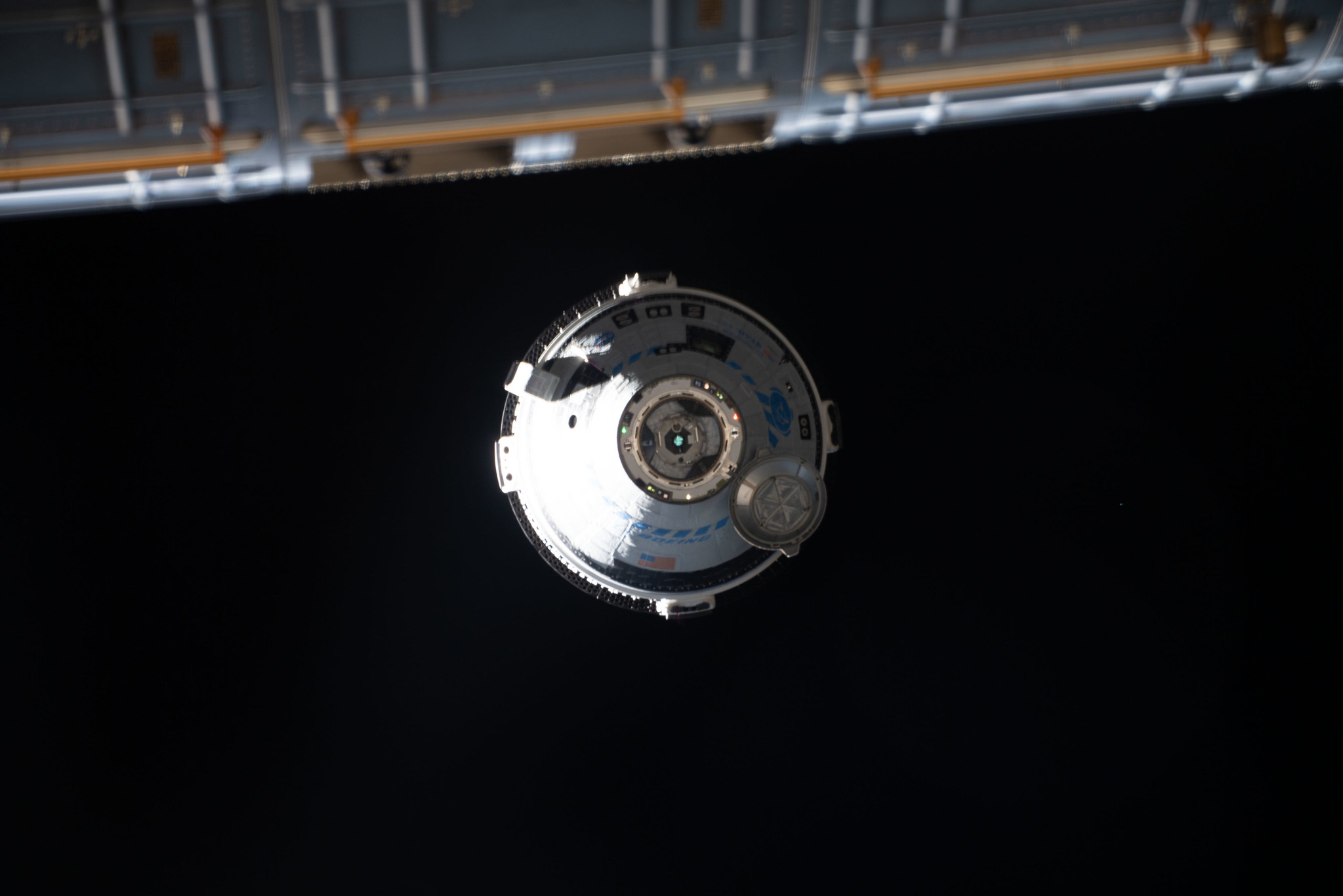
NASA Sets Coverage for Boeing Starliner’s First Crewed Launch, Docking
NASA will provide live coverage of prelaunch and launch activities for the agency’s Boeing Crew Flight Test, which will carry NASA astronauts Butch Wilmore and Suni Williams to and from the International Space Station.
Launch of the ULA (United Launch Alliance) Atlas V rocket and Boeing Starliner spacecraft is targeted for 9:34 p.m. CDT May 6, from Space Launch Complex-41 at Cape Canaveral Space Force Station.
Boeing’s Starliner spacecraft approaches the International Space Station. NASA astronauts Butch Wilmore and Suni Williams will launch aboard Starliner on a United Launch Alliance Atlas V rocket for NASA’s Boeing Crew Flight Test.
Credits: NASA
The flight test will carry Wilmore and Williams to the space station for about a week to test the Starliner spacecraft and its subsystems before NASA certifies the transportation system for rotational missions to the orbiting laboratory for the agency’s Commercial Crew Program.
The HOSC (Huntsville Operations Support Center) at NASA’s Marshall Space Flight Center provides engineering and mission operations support for the space station, the Commercial Crew Program, and Artemis missions, as well as science and technology demonstration missions.
Starliner will dock to the forward-facing port of the station’s Harmony module at 11:48 p.m., May 8.
NASA’s mission coverage is as follows (all times Central and subject to change based on real-time operations):
May 3 11:30 a.m. – Prelaunch news conference at Kennedy (no earlier than one hour after completion of the Launch Readiness Review) with the following participants:
NASA Administrator Bill Nelson
Steve Stich, manager, NASA’s Commercial Crew Program
Dana Weigel, manager, NASA’s International Space Station Program
Emily Nelson, chief flight director, NASA
Jennifer Buchli, chief scientist, NASA’s International Space Station Program
Mark Nappi, vice president and program manager, Commercial Crew Program, Boeing
Gary Wentz, vice president, Government and Commercial Programs, ULA
Brian Cizek, launch weather officer, 45th Weather Squadron, Cape Canaveral Space Force Station
Coverage of the prelaunch news conference will stream live on NASA+, NASA Television, the NASA app, YouTube, and the agency’s website.
2:30 p.m. – NASA Social panel live stream event at Kennedy with the following participants:
Ian Kappes, deputy launch vehicle office manager, NASA’s Commercial Crew Program
Amy Comeau Denker, Starliner associate chief engineer, Boeing
Caleb Weiss, system engineering and test leader, ULA
Jennifer Buchli, chief scientist, NASA’s International Space Station Program
Coverage of the panel live stream event will stream live at @NASAKennedy on YouTube, @NASAKennedy on X, and @NASAKennedy on Facebook. Members of the public may ask questions online by posting questions to the YouTube, X, and Facebook livestreams using #AskNASA.
May 6
5:30 p.m. – Launch coverage begins on NASA+, NASA Television, the NASA app, YouTube, and the agency’s website.
9:34 p.m. – Launch
Launch coverage on NASA+ will end shortly after Starliner orbital insertion. NASA Television will provide continuous coverage leading up to docking and through hatch opening and welcome remarks.
All times are estimates and could be adjusted based on operations after launch. Follow the space station blog for the most up-to-date operations information.
NASA will provide a live video feed of Space Launch Complex-41 approximately 48 hours prior to the planned liftoff of the mission. Pending unlikely technical issues, the feed will be uninterrupted until the prelaunch broadcast begins on NASA Television, approximately four hours prior to launch. Once the feed is live, find it here: http://youtube.com/kscnewsroom.
Launch day coverage of the mission will be available on the agency’s website. Coverage will include live streaming and blog updates beginning no earlier than 5:30 p.m., May 6 as the countdown milestones occur. On-demand streaming video and photos of the launch will be available shortly after liftoff.
NASA Selects BAE Systems to Develop Air Quality Instrument for NOAA
Smog over a deep mountain valley.
Credit: NOAA
NASA, on behalf of the National Oceanic and Atmospheric Administration (NOAA), has selected BAE Systems (formerly known as Ball Aerospace & Technologies Corporation) of Boulder, Colorado, to develop an instrument to monitor air quality and provide information about the impact of air pollutants on Earth for NOAA’s Geostationary Extended Observations (GeoXO) satellite program.
This cost-plus-award-fee contract is valued at approximately $365 million. It includes the development of one flight instrument as well as options for additional units. The anticipated period of performance for this contract includes support for 10 years of on-orbit operations and five years of on-orbit storage, for a total of 15 years for each flight model. The work will take place at BAE Systems, NASA’s Goddard Space Flight Center in Greenbelt, Maryland, and the agency’s Kennedy Space Center in Florida.
The GeoXO Atmospheric Composition (ACX) instrument is a hyperspectral spectrometer that measures a wide spectrum of light from ultraviolet to visible. The instrument will provide hourly observations of air pollutants emitted by transportation, power generation, industry, oil and gas extraction, volcanoes, and wildfires as well as secondary pollutants generated from these emissions once they are in the atmosphere. By providing continuous observations and measurements of atmospheric composition, ACX data will improve air quality forecasting and monitoring and mitigate health impacts from severe pollution and smoke events, such as asthma, cardiovascular disease, and neurological disorders. Data from ACX also will help scientists better understand linkages between weather, air quality and climate.
The contract scope includes the tasks and deliverables necessary to design, analyze, develop, fabricate, integrate, test, verify, evaluate, support launch, supply and maintain the instrument ground support equipment, and support mission operations at the NOAA Satellite Operations Facility in Suitland, Maryland.
The GeoXO program is the follow-on to the Geostationary Operational Environmental Satellites – R (GOES-R) Series Program.
The GeoXO satellite system will advance Earth observations from geostationary orbit. The mission will supply vital information to address major environmental challenges of the future in support of weather, ocean, and climate operations in the United States. Advanced capabilities from GeoXO will help address our changing planet and the evolving needs of NOAA’s data users. NOAA and NASA are working to ensure these critical observations are in place by the early 2030s when the GOES-R Series nears the end of its operational lifetime.
Together, NOAA and NASA will oversee the development, launch, testing, and operation of all the satellites in the GeoXO program. NOAA funds and manages the program, operations, and data products. On behalf of NOAA, NASA and commercial partners develop and build the instruments and spacecraft and launch the satellites.